
Decoding the Electric Water Heater Wiring Schematic
Planning the electrical infrastructure for a water heater requires more than simply pulling a cable and making a connection. Whether you are upgrading to a high-efficiency hybrid unit or replacing a standard 40-gallon tank, understanding the underlying electric water heater wiring schematic is critical for safety, code compliance, and long-term reliability. In 2026, the landscape of residential water heating has shifted heavily toward Heat Pump Water Heaters (HPWHs) and smart-grid-connected units, making pre-installation planning more complex than ever.
This guide provides a comprehensive installation planning matrix, breaking down standard 240V non-simultaneous schematics, National Electrical Code (NEC) requirements, and specific routing strategies for modern appliances.
The Standard 240V Non-Simultaneous Schematic Explained
The vast majority of traditional residential electric storage water heaters operate on a 240V, non-simultaneous circuit. This means the upper and lower heating elements never draw power at the exact same time, which keeps the peak amperage draw manageable for standard residential panels.
Power Flow Logic
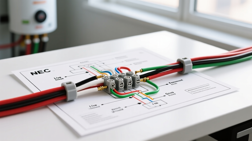
- Line 1 (L1): Enters the upper thermostat. The upper thermostat acts as the primary gatekeeper. If the top of the tank is cold, L1 power is routed through the upper element. Once the top reaches the setpoint, the upper thermostat 'flips' the internal switch, transferring L1 power down to the lower thermostat.
- Line 2 (L2): Bypasses the thermostats entirely and is wired directly to the opposite terminal of both the upper and lower heating elements.
- Ground (Bare/Green): Bonds directly to the tank chassis and the green grounding screw on the water heater's junction box. It never passes through a thermostat or heating element.
Expert Insight: A common mistake among DIYers is assuming both elements fire simultaneously to heat the water faster. If you attempt to wire a standard residential tank for simultaneous operation, you will immediately trip a 30A breaker and risk melting 10 AWG wire insulation. Always verify the schematic on the inside of the manufacturer's junction box cover.
Pre-Installation Planning Matrix: Sizing & NEC Compliance
According to the National Fire Protection Association (NFPA), NEC Article 422.13 dictates that storage-type water heaters with a capacity of 120 gallons or less must be considered a continuous load for branch circuit sizing. This mandates that the circuit be rated for at least 125% of the nameplate load.
| Heater Type | Element Wattage | Voltage | Base Amperage | 125% NEC Multiplier | Min. Copper Wire | Breaker Size |
|---|---|---|---|---|---|---|
| Standard 40-Gal Tank | 4500W | 240V | 18.75A | 23.4A | 10 AWG NM-B | 30A 2-Pole |
| Standard 50-Gal Tank | 5500W | 240V | 22.9A | 28.6A | 10 AWG NM-B | 30A 2-Pole |
| Hybrid Heat Pump (e.g., Rheem ProTerra) | 1500W (Elements) | 240V | 15A (Max) | 18.75A | 12 AWG NM-B | 20A 2-Pole |
| Point-of-Use (Under Sink) | 1500W | 120V | 12.5A | 15.6A | 12 AWG NM-B | 20A 1-Pole (GFCI) |
Note: Always verify the specific nameplate data of your exact model. Manufacturers like Bradford White and AO Smith occasionally release high-recovery models that require 40A circuits and 8 AWG wire.
Conduit Strategy and Wire Routing Specifics
When planning the physical route from your main service panel to the water heater location, the environment dictates your wiring method.
Interior Drywall Runs
For standard interior runs through wooden studs, 10/2 NM-B (Romex) with ground is the industry standard. Ensure the cable is stapled within 8 inches of the panel and the water heater junction box, and secured every 4.5 feet along the run. If the cable runs through a garage or an area subject to physical damage, it must be protected by running it through 1/2-inch EMT conduit or routing it behind drywall.
Masonry, Concrete, and Outdoor Runs
If you are wiring a water heater in a basement with exposed concrete walls, a detached garage ADU, or an outdoor utility closet, NM-B is prohibited. You must use individual THHN/THWN-2 conductors inside a raceway.
- Conduit Sizing: Two 10 AWG THHN wires plus a 10 AWG green ground wire will easily fit inside 1/2-inch PVC Schedule 80 or 1/2-inch EMT.
- Bend Radius: Limit conduit bends to no more than 360 degrees between pull points to prevent insulation scoring during the pull.
- Voltage Drop: For runs exceeding 50 feet, upsizing to 8 AWG copper is highly recommended to maintain voltage drop below the NEC suggested 3% threshold, ensuring your elements operate at peak efficiency and do not degrade prematurely.
Heat Pump Water Heater (HPWH) Schematic Variations
The transition toward electrification has made Heat Pump Water Heaters the standard for new construction in many jurisdictions. According to the U.S. Department of Energy, HPWHs can be up to three times more energy-efficient than conventional electric resistance models. However, their internal schematics are vastly different.
Units like the Rheem ProTerra or AO Smith Voltex feature integrated compressors, evaporator fans, and defrost control boards. While they still connect to a 240V source, the internal logic board manages power distribution to the compressor and the backup resistance elements. Critical Planning Note: Many HPWHs require a dedicated 20A or 30A 240V circuit, but they also feature a CTA-2045 communication port. If you are integrating the unit into a smart panel (like a SPAN panel) or a utility demand-response program, you must plan for low-voltage Cat6 or specialized communication wiring alongside your high-voltage conduit.
Terminations, Torque, and Pre-Energization Testing
The most frequent point of failure in water heater installations is a loose termination at the heating element or thermostat. A loose connection creates high resistance, leading to localized heat buildup, melted wire nuts, and eventual arcing.
- Stripping: Strip exactly 3/4-inch of insulation from the 10 AWG conductors. Do not nick the copper conductor, as this creates a weak point that can snap under thermal expansion.
- Torque: Use a calibrated torque screwdriver. Most water heater element screws and thermostat terminals require between 14 to 16 inch-pounds of torque. Overtightening can strip the brass threads; undertightening guarantees a thermal failure.
- Continuity Check: Before turning the breaker on, set your multimeter to the Ohms (Ω) setting. Place probes across the terminals of the upper and lower elements. A healthy 4500W element should read between 12 and 13 ohms. A reading of 'OL' (Open Loop) indicates a blown element that must be replaced before energizing.
Expert Troubleshooting & Edge Cases
The 'Same Phase' Trap
If you are installing a new 2-pole breaker in an older panel, ensure the breaker connects to both the A and B bus bars. If a 2-pole breaker is improperly installed or if you attempt to use two single-pole breakers tied together on the same phase leg, you will only have 0V potential across the heating elements. The water heater will appear to have power (120V to ground), but the elements will never heat.
GFCI and AFCI Requirements
Under recent NEC updates adopted widely through 2026, standard 240V water heaters located in unfinished basements or garages may require GFCI or AFCI protection depending on local jurisdiction amendments. Always verify with your local Authority Having Jurisdiction (AHJ). If required, use a dedicated 2-pole GFCI breaker, ensuring the neutral pigtail is connected to the panel's neutral bar, even if the water heater itself does not utilize a neutral wire.
Summary Checklist for the Electrical Contractor
- Verify nameplate wattage and calculate 125% continuous load requirement.
- Confirm 240V 2-pole breaker sizing (typically 30A for standard, 20A for hybrid).
- Route 10/2 NM-B or THHN in conduit, upsizing to 8 AWG for runs over 50 feet.
- Torque all element and thermostat connections to 14-16 in-lbs.
- Perform ohm continuity checks on elements prior to energizing the circuit.
For further reference on breaker sizing and load calculations, consult the Schneider Electric / Square D sizing guidelines to ensure your main service panel has the spare capacity to handle the new continuous load without violating the 80% panel capacity rule.