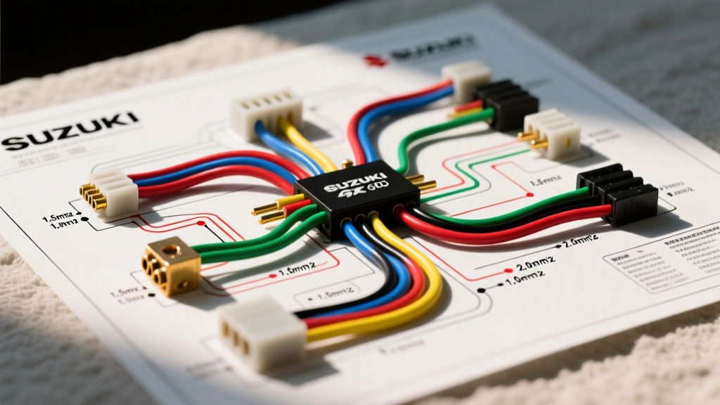

Introduction: Navigating the GSX-R 600 Electrical Labyrinth
Whether you are restoring a 2006 K6 model, upgrading the charging system on a 2008 K8, or diagnosing a drive-by-wire fault on a 2011+ L-series, interpreting the wiring diagram for Suzuki GSXR 600 is a mandatory skill for any serious sportbike mechanic. Unlike standard automotive applications that rely on SAE or DIN standards, Suzuki utilizes Japanese Industrial Standards (JIS) for both wire color coding and metric cross-sectional area gauges. Misinterpreting these standards often leads to undersized replacement wires, melted connectors, and catastrophic ECU failures.
In 2026, with OEM replacement harnesses for the GSX-R 600 frequently exceeding $750 to $950 depending on the exact sub-model and dealer markup, learning to trace, repair, and upgrade your factory loom using the correct metric wire and JIS color codes is not just a technical exercise; it is a massive cost-saving measure. This guide bridges the gap between the factory service manual schematics and real-world bench repair, focusing heavily on wire gauge translation and color code identification.
Understanding JIS Color Codes in Suzuki Harnesses
The Japanese Automotive Standards Organization (JASO) and JIS dictate the color palette used in Suzuki wiring harnesses. The factory wiring diagram for Suzuki GSXR 600 models will list colors using a base color and a tracer (stripe) color, usually abbreviated with a slash (e.g., B/W for Black with a White tracer). Understanding these abbreviations is the first step to accurate circuit tracing.
Primary JIS Color Abbreviations
- B: Black (Typically main ground or switched ground)
- W: White (Often used for sensor signals or 5V references)
- R: Red (Unswitched battery positive, 12V constant)
- O: Orange (Switched 12V positive, ignition controlled)
- Y: Yellow (AC output from the stator, pre-rectifier)
- G: Green (Often used for lighting circuits or specific sensor grounds)
- L: Blue (Turn signals, ECU communication lines)
- Br: Brown (Tail lights, license plate illumination)
Expert Insight: On the GSX-R 600, never assume a solid Black wire is always a ground in the sensor sub-harness. While B/W is universally ground, solid Black is occasionally used as a signal return for specific Hall-effect sensors on the L1+ drive-by-wire throttle bodies. Always verify with a multimeter against the factory pinout.
Common GSX-R 600 Circuit Color Mapping
| Circuit Function | Factory Wire Color(s) | JIS Abbreviation | Voltage/Signal Type |
|---|---|---|---|
| Main Battery Feed | Red | R | 12V DC Constant |
| Ignition Switch Output | Orange/White | O/W | 12V DC Switched |
| Stator 3-Phase Output | Yellow (x3) | Y | 30V-70V AC (RPM dependent) |
| ECU Sensor Ground | Black/White | B/W | 0V DC Reference |
| Throttle Position Sensor (TPS) | White/Red, Black/White | W/R, B/W | 0-5V DC Analog |
| Injector Trigger (Cyl 1-4) | Various (e.g., Br/W, L/W) | Br/W, L/W | 12V Pulsed DC (Ground side) |
Wire Gauge Metrics: Translating AVSS to AWG
One of the most critical errors made by DIY mechanics consulting the wiring diagram for Suzuki GSXR 600 is attempting to replace metric wire with standard American Wire Gauge (AWG) spool wire without calculating the cross-sectional area. Suzuki uses AV, AVS, and AVSS (Automotive Vinyl insulated, Super-thin) wire types. AVSS wire is heavily used in modern GSX-R harnesses to save weight and space, featuring a much thinner insulation wall than standard AWG primary wire.
Metric to AWG Conversion Chart for GSX-R Repair
When sourcing replacement wire for your loom, you must match the cross-sectional area (mm²) to handle the specific amperage of the circuit. Below is the translation chart for the most common sizes found in the GSX-R 600 harness.
| Suzuki Metric Size (mm²) | AWG Equivalent (Approx) | Max Ampacity (Chassis Wiring) | Common GSX-R 600 Application |
|---|---|---|---|
| 0.5f (0.5 mm²) | 22 AWG | 4 - 5 Amps | ECU sensors, TPS, MAP sensor, temp sensors |
| 0.85 (0.85 mm²) | 18 AWG | 8 - 10 Amps | Tail lights, dash illumination, ECU triggers |
| 1.25 (1.25 mm²) | 16 AWG | 12 - 15 Amps | Turn signals, horn, cooling fan trigger |
| 2.0 (2.0 mm²) | 14 AWG | 18 - 20 Amps | Ignition coils, headlight high/low beam, fuel pump |
| 3.0 (3.0 mm²) | 12 AWG | 25 - 30 Amps | Main harness feed, starter relay control |
| 5.5 (5.5 mm²) | 10 AWG | 40 - 50 Amps | Stator to Rectifier output (upgraded) |
| 8.0 (8.0 mm²) | 8 AWG | 60 - 70 Amps | Battery to starter solenoid, main ground |
For authoritative data on wire resistance and ampacity limits across different gauges, refer to the comprehensive AWG wire sizing charts provided by the Engineering Toolbox. When repairing sensor circuits, always use PTFE (Teflon) or high-grade AVSS wire to prevent voltage drop, which can cause the GSX-R's ECU to throw false lean-condition or TPS correlation codes.
Critical Circuit Analysis: The 3-Phase Stator and Rectifier
No discussion of the GSX-R 600 electrical system is complete without addressing the notorious 3-phase charging system. Across almost all generations of the GSX-R 600, the stator outputs three Yellow (Y) wires that plug into the regulator/rectifier. The factory wiring diagram shows these as simple point-to-point connections, but the physical reality is a known failure point.
The 'Melting Connector' Failure Mode
The factory stator connector uses standard brass terminals inside a plastic housing. Over time, engine vibration and thermal cycling cause the crimps on the 14 AWG (2.0 mm²) yellow wires to loosen. This increases electrical resistance. Because the stator can output upwards of 35-40 Amps at high RPM, this resistance generates immense heat, melting the plastic connector and eventually burning out the stator windings.
The 2026 MOSFET Upgrade Protocol
If you are using the wiring diagram to perform a charging system upgrade, bypass the factory plastic connector entirely. Follow this protocol:
- Cut and Strip: Cut the factory connector off the stator side and the rectifier side. Strip back 8mm of insulation on the three Yellow wires.
- Upgrade Wire: If the factory wires show signs of heat discoloration, splice in new 12 AWG (3.0 mm²) high-temperature silicone wire for the run from the engine case to under the seat.
- Use High-Amp Terminals: Crimp 30A continuous-rated, nickel-plated bullet connectors onto the wires. Do not use standard brass bullets.
- Seal the Connection: Slide adhesive-lined, dual-wall heat shrink tubing over the bullet connections. When heated, the inner adhesive melts and creates a waterproof, vibration-proof seal.
- Install MOSFET Regulator: Upgrade to an aftermarket MOSFET regulator (such as those from Rick's Motorsport Electrics). MOSFET technology runs significantly cooler than the factory Shunt-style regulator and handles the GSX-R's high-RPM AC ripple far more efficiently.
Tracing the ECU and Sensor Sub-Harness
The L1 (2011) and newer GSX-R 600 models introduced a complex drive-by-wire (DBW) system and a highly sensitive Denso ECU. When using the wiring diagram to trace DBW faults, you are dealing with redundant sensor circuits. The Accelerator Position Sensor (APS) and Throttle Position Sensor (TPS) both utilize dual-track potentiometers.
For example, the APS will have a 5V reference (usually White/Red), a sensor ground (Black/White), and two signal return wires (often Green/White and Blue/White). The ECU expects the voltage on signal track 1 to be exactly inverse or mathematically proportional to track 2. If you repair a broken wire in this sub-harness using the wrong gauge or a poor solder joint, the added resistance will skew the voltage by just 0.1V, causing the ECU to trigger a 'FI' (Fuel Injection) dash error and put the bike into limp mode.
Diagnostic Tip: Never use a standard test light or an unbuffered multimeter on the 5V ECU reference wires. The low impedance of a test light can backfeed the ECU driver circuit and fry the internal 5V voltage regulator. Always use a high-impedance digital multimeter (minimum 10 Megohm input impedance) when probing these circuits.
Best Practices for Loom Repair and Crimping
When executing repairs based on the wiring diagram, the physical termination of the wire is just as critical as the routing. Japanese unsealed connectors (like those used for the dash, ECU, and lighting) use specific JST or Sumitomo 090-series terminals.
- Tooling: Avoid cheap, universal crimpers. Invest in a dedicated ratcheting crimper designed for Japanese automotive terminals, such as the Glarks SN-28B or the Titan 11477. These tools feature die profiles that match the Sumitomo 090 wings perfectly, ensuring a gas-tight crimp.
- Soldering vs. Crimping: Never solder wires inside the engine bay or near the exhaust headers. Solder wicks up under the insulation via capillary action, creating a rigid point that will snap under the high-frequency vibration of an inline-four engine. Always use a proper mechanical crimp, followed by adhesive-lined heat shrink.
- Wire Loom Protection: The factory harness uses cross-woven PET expandable sleeving. When repairing a section, wrap the repaired wires in Tesa 51036 PET cloth tape. This tape is rated for 150°C continuous heat, making it ideal for the tight, hot confines of the GSX-R 600 frame spar and airbox area.
Frequently Asked Questions (FAQ)
Can I use standard 18 AWG wire to replace a 0.85f metric wire on the GSX-R?
While 18 AWG (0.82 mm²) is very close to 0.85f, standard 18 AWG primary wire has much thicker PVC insulation than Suzuki's AVSS wire. If you use standard 18 AWG, the bundle will become too thick to fit inside the factory rubber loom boots and connector housings, leading to pinched wires and short circuits. Always source thin-wall AVS or AVSS equivalent wire for harness repairs.
Why does my wiring diagram show a 'B/W' wire going to a 12V component?
In some specific lighting and relay circuits on older K-series GSX-R models, Suzuki uses Black/White as a switched ground trigger rather than a positive feed. The component receives constant 12V from an Orange wire, and the ECU or turn signal relay completes the circuit by grounding the B/W wire. Always verify the presence of 12V at the component before assuming the B/W wire is the positive supply.
Where can I find the OEM connector pinouts for the main ECU plug?
While the general wiring diagram provides circuit routing, exact 48-pin or 60-pin ECU connector face views are usually located in the very back of the official Suzuki Service Manual under the 'Electrical Data' appendix. Alternatively, specialized OEM parts fiche sites like CMSNL provide exploded views of the harness assemblies, which can help identify specific sub-connector part numbers and routing paths.