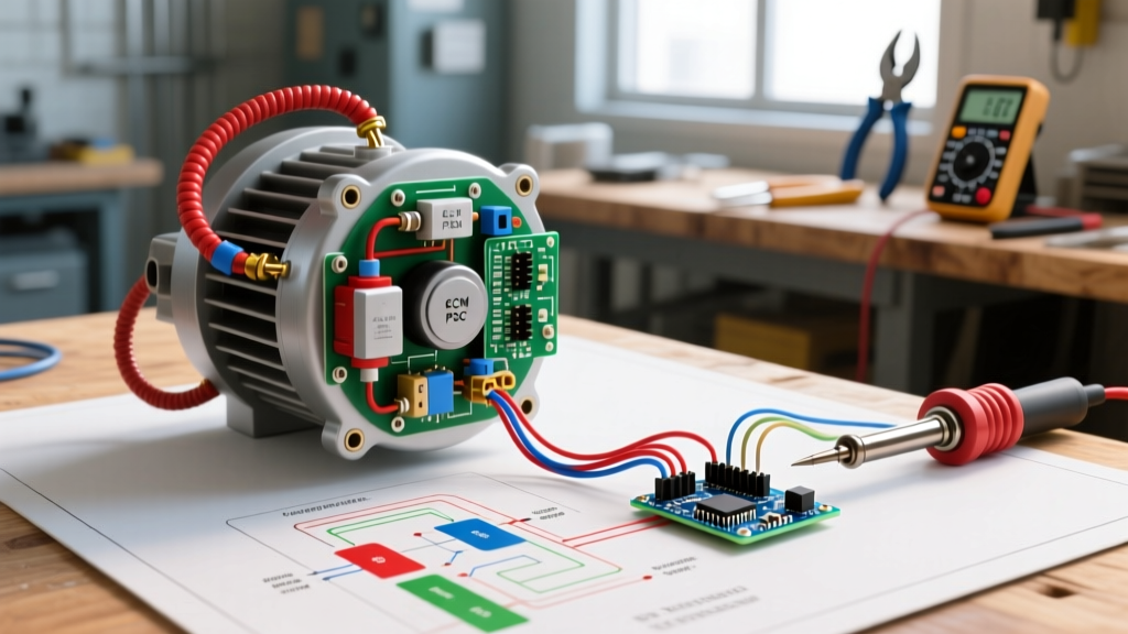

Mastering the Furnace Wiring Diagram for Blower Motor Troubleshooting
When an HVAC system fails to move air, the blower motor is the prime suspect. However, blindly swapping out a $300 motor without verifying the control logic is a costly mistake. To accurately diagnose the issue, you must understand how to read a furnace wiring diagram for blower motor circuits. These schematics, typically located on the inside of the blower compartment access panel, are your roadmap for tracing line voltage, low-voltage thermostat calls, and internal relay logic.
In 2026, the HVAC landscape is heavily skewed toward high-efficiency Electronically Commutated Motors (ECMs) due to updated Department of Energy (DOE) mandates, though legacy Permanent Split Capacitor (PSC) motors remain in millions of homes. This guide provides a deep-dive, expert-level framework for using wiring diagrams to isolate blower motor failures across both platforms.
CRITICAL SAFETY WARNING: Before opening the blower compartment or touching any terminals, disconnect the main power at the service disconnect switch or breaker panel. Verify zero energy using a CAT III or CAT IV rated multimeter (such as the Fluke 116 HVAC) between L1 and Neutral, and L1 and Ground. Refer to OSHA electrical safety guidelines for proper lockout/tagout procedures.
Anatomy of the Blower Motor Schematic
Every manufacturer—from Carrier and Lennox to Trane and Goodman—uses standardized NEMA and IEC symbols on their diagrams. When tracing a fault, you must first identify the three primary circuit zones on the schematic:
- Line Voltage Circuit (120V/240V): Traced with heavy lines. Includes the main power input (L1, L2 or L1, N), the transformer primary, the blower motor windings, and the run capacitor.
- Low Voltage Control Circuit (24VAC): Traced with lighter lines. Includes the transformer secondary (SEC), thermostat terminals (R, W, Y, G, C), and the control board micro-relays.
- Component Logic & Safeties: Includes high-limit switches, pressure switches, and the blower relay or triac switches on the Integrated Furnace Control (IFC) board.
Decoding the Legend
Do not skip the legend box, usually located in the bottom right corner of the diagram. It defines factory-installed wiring (solid lines) versus field-installed wiring (dashed lines). It also specifies the exact microfarad (MFD) rating for the run capacitor and the thermal overload reset temperature for the motor windings.
PSC vs. ECM: Reading the Diagram Differences
The troubleshooting approach changes drastically depending on the motor type. According to Energy.gov furnace efficiency standards, newer systems mandate higher SEER2 and AFUE ratings, pushing ECMs to market dominance. Here is how their wiring schematics differ:
| Feature | PSC (Permanent Split Capacitor) | ECM (Electronically Commutated Motor) |
|---|---|---|
| Schematic Complexity | Simple (Motor, Capacitor, Relay) | Complex (Motor Module, 5-pin harness, Thermistor) |
| Line Voltage Inputs | 120V AC (L1 and Neutral) | 120V or 240V AC (L1, L2 or L1, N depending on model) |
| Control Signal | 120V applied directly to windings via relay | 24V AC logic signals or PWM from IFC board |
| Common Failure Point | Run Capacitor (e.g., 10 MFD, 370V) | Control Module (e.g., Genteq 5M or X13) |
| Average 2026 Replacement Cost | $85 - $150 (Motor) + $15 (Capacitor) | $250 - $450 (Module) or $600+ (Full Motor) |
Step-by-Step PSC Blower Motor Troubleshooting
If your diagram shows a standard 3-wire or 4-wire PSC motor connected to a run capacitor, follow this diagnostic sequence using your multimeter.
1. Verify the Thermostat 'G' Call
Set your thermostat to FAN ON. Using your multimeter set to VAC, measure between the R and G terminals on the control board. You should read between 24V and 28V AC. If voltage is absent, the fault is in the low-voltage thermostat wiring, not the blower circuit.
2. Trace the Blower Relay on the IFC
Locate the blower relay on the schematic. When the 'G' call is active, the IFC energizes the relay coil. Measure for 120V AC between the HEAT or COOL speed tap on the control board and the Neutral bus bar. If you have 24V at the 'G' terminal but no 120V output from the board, the internal micro-relay has failed. Solution: Replace the IFC board (e.g., Carrier HK31EA or Lennox 103267-01).
3. Test the Run Capacitor
A PSC motor will hum but fail to start if the capacitor is weak. Disconnect power, safely discharge the capacitor using a 20,000-ohm, 5-watt resistor, and disconnect the wires. Switch your multimeter to capacitance (MFD). A 10 MFD capacitor with a +/- 6% tolerance should read between 9.4 and 10.6 MFD. If it reads below 9.0 MFD, or shows physical bulging, replace it immediately.
4. Winding Resistance Test
Disconnect the motor wires from the board and capacitor. Measure resistance (Ohms) between the Common (C), Start (S), and Run (R) terminals. The mathematical rule is: Resistance (C to S) + Resistance (C to R) = Resistance (S to R). If you read infinite resistance (OL) between any two terminals, the internal thermal overload has tripped or a winding is open. Allow the motor to cool for 60 minutes; if it remains open, the motor is dead.
Advanced ECM Blower Motor Diagnostics
Troubleshooting an ECM (like the ubiquitous Regal Beloit Genteq X13 or 3.0 series) using a furnace wiring diagram requires a different methodology. The diagram will show a 5-pin low-voltage harness and a 3-pin or 4-pin line voltage harness.
- Verify Line Voltage: ECM modules require constant line voltage to keep the internal microprocessor alive. Check for 120V/240V at the main power harness. A dropped neutral in the home's electrical panel can send 240V through a 120V ECM circuit, instantly frying the module's varistor.
- Check the 24V AC Logic: Unlike PSC motors, ECMs use 24V AC signals on the 5-pin harness to dictate speed. For example, on a standard X13 motor, applying 24V between the 'C' and 'G' pins commands the cooling speed. If the IFC board sends the 24V signal but the motor does not ramp up, the module is likely faulty.
- Thermistor Verification: Many ECM diagrams include an external thermistor attached to the evaporator coil or heat exchanger. Measure the thermistor's resistance. At 70°F (21°C), it should read approximately 10k ohms. A skewed reading will cause the ECM to default to a low-speed safety mode.
Real-World Edge Cases and Failure Modes
Wiring diagrams do not always account for environmental degradation. Here are two edge cases frequently encountered by senior technicians:
The 'Phantom' Voltage Drop
You measure 120V at the control board output, but the PSC motor won't start. When you measure under load (with the motor connected), the voltage drops to 40V. This indicates a high-resistance connection, usually a corroded Molex plug or a loose spade connector on the IFC board. The diagram shows a continuous wire, but the physical connection is failing. Always perform voltage-drop tests under load.
Control Board DIP Switch Mismatch
When replacing an IFC board, technicians often forget to replicate the factory DIP switch settings shown on the wiring diagram's configuration table. If a 40,000 BTU furnace is incorrectly set to the 80,000 BTU profile via the DIP switches, the blower will run at an incorrect CFM, causing the high-limit switch to trip repeatedly. Always cross-reference the schematic's setup matrix.
Conclusion
Reading a furnace wiring diagram for blower motor troubleshooting is not about memorizing every wire color; it is about understanding the logical flow of power from the transformer to the relay, and finally to the motor windings or ECM module. By combining schematic literacy with precise multimeter diagnostics, you can accurately pinpoint whether a failure lies in a $15 capacitor, a $150 control board, or a $400 ECM module. For further reading on HVAC efficiency and electrical standards, consult the EPA Energy Star HVAC guidelines.
Frequently Asked Questions (FAQ)
Why does my furnace wiring diagram show two different speed taps for heating?
Many older furnaces use a lower speed tap (e.g., Red wire) for standard heating, and a medium speed tap (e.g., Blue wire) for heat pump auxiliary heat or continuous fan circulation. This ensures proper CFM for different BTU outputs.
Can I bypass the control board to test the blower motor directly?
Yes, for a PSC motor, you can temporarily apply 120V directly to the Common and Run windings (with the capacitor connected) to verify if the motor spins. Never apply 120V directly to the 5-pin low-voltage harness of an ECM motor, as this will permanently destroy the module.
What does 'SEC' and 'PRI' mean on the transformer in the diagram?
PRI stands for Primary (the 120V/240V line voltage input side), and SEC stands for Secondary (the 24V AC low-voltage output side that powers the thermostat and control board logic).