
The Role of 3-Phase Starters in Heavy-Duty & Electric Vehicles
When most people think of vehicle electrical systems, they picture 12V or 24V DC circuits. However, the rapid expansion of Class 8 electric trucks, heavy-duty electric forklifts, and marine expedition vehicles has fundamentally changed the mobile electrical landscape. In these heavy-duty electric vehicles (EVs), auxiliary systems—such as hydraulic steering pumps, air brake compressors, and high-capacity HVAC units—frequently rely on 480V AC or 340V DC-to-AC inverted 3-phase induction motors. Understanding the wiring diagram for motor starter 3 phase configurations in a mobile environment is critical for EV technicians, conversion specialists, and marine electricians.
Unlike static industrial panels, vehicle-mounted 3-phase motor starters must endure severe vibration, thermal cycling, and voltage fluctuations inherent to mobile powertrains. This guide breaks down the exact wiring architecture, component sizing, and mobile-specific failure modes for 3-phase motor starters in electric commercial vehicles and auxiliary EV systems.
Core Components: Sizing Contactors for Mobile Applications
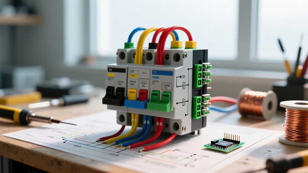
In a heavy-duty EV or marine vessel, the 3-phase motor starter is typically housed in a sealed, vibration-dampened auxiliary power distribution unit (APDU). The starter assembly consists of a main disconnect, fuses or a motor protection circuit breaker (MPCB), a 3-pole magnetic contactor, and a bimetallic or solid-state overload relay.
According to the National Electrical Manufacturers Association (NEMA), contactors are classified by size based on horsepower and voltage ratings. For a 480V AC auxiliary hydraulic pump in an electric bus or airport ground support vehicle, you must select a contactor that can handle the high inrush current (Locked Rotor Amps) without contact welding.
NEMA Contactor Sizing Matrix for 480V EV Auxiliary Motors
| Motor HP | FLA (Amps) | NEMA Size | Recommended Contactor | Wire Gauge (THHN) | Terminal Torque Spec |
|---|---|---|---|---|---|
| 3 HP | 4.8 A | Size 1 | Eaton C25DND310 (30A) | 12 AWG | 1.2 Nm (11 in-lbs) |
| 7.5 HP | 11 A | Size 1 | Siemens SIRIUS 3RT2026 | 10 AWG | 1.5 Nm (13 in-lbs) |
| 15 HP | 21 A | Size 2 | Schneider TeSys LC1D25 | 8 AWG | 2.5 Nm (22 in-lbs) |
| 30 HP | 40 A | Size 3 | Eaton C25DND350 (50A) | 4 AWG | 4.5 Nm (40 in-lbs) |
Step-by-Step: Wiring Diagram for Motor Starter 3 Phase (EV Auxiliary Pump)
Wiring a 3-phase starter in a vehicle requires managing two distinct circuits: the Power Circuit (carrying the high-voltage 3-phase AC from the vehicle's inverter or shore-power isolation transformer) and the Control Circuit (usually stepping down from the vehicle's 24V DC chassis battery to trigger an interposing relay, which then fires the high-voltage AC contactor coil).
1. The Power Circuit Wiring Flow
- Source Isolation: Connect the 3-phase lines (L1, L2, L3) from the EV's auxiliary inverter to a lockable rotary disconnect switch. This is a strict OSHA and NFPA 70E requirement for mobile maintenance safety.
- Short Circuit Protection: Route L1, L2, and L3 through Class RK5 time-delay fuses or a Siemens 3RV2 MPCB. Size the fuses at 175% of the motor's Full Load Amps (FLA) to accommodate startup surges.
- Contactor Lugs: Terminate the protected lines into the top (line-side) terminals of the 3-pole contactor. Pro-Tip: Use Belleville (conical) washers under the terminal lugs. In high-vibration vehicle environments, these washers maintain constant tension as copper expands and contracts during thermal cycling.
- Overload Relay: Wire the bottom (load-side) of the contactor to the input of the thermal overload relay (e.g., Eaton C306 or Schneider LRD series). Set the dial exactly to the motor's nameplate FLA.
- Motor Termination: Run 3-conductor shielded cable from the overload relay to the motor junction box, terminating in T1, T2, and T3. Ensure the shielding is grounded to the vehicle chassis to prevent electromagnetic interference (EMI) with the EV's CAN bus networks.
2. The Control Circuit Wiring Flow
In mobile applications, you rarely run 480V to a dashboard switch. Instead, you use a low-voltage DC control logic.
- Run a 24V DC signal from the vehicle's ignition or ECU to a solid-state interposing relay (e.g., Phoenix Contact PLC-RSC).
- The interposing relay switches a 120V AC or 240V AC control voltage (derived from a step-down transformer) to the A1 and A2 coil terminals of the main 3-phase contactor.
- Wire the Normally Closed (NC) auxiliary contact of the thermal overload relay in series with the contactor coil. If the motor overheats, the NC contact opens, dropping the coil voltage and instantly severing power to the motor.
Expert Insight: In custom EV conversions, never wire a 3-phase contactor coil directly to a 12V/24V DC battery source unless the contactor is specifically rated for DC coil operation (like the Gigavac GV200 series). Standard industrial contactors use AC coils; applying DC will cause the coil to draw excessive current and burn out within seconds.
Common Failure Modes in Mobile & Vehicular Environments
Industrial motor starters are designed to sit in climate-controlled electrical rooms. When you mount them inside the chassis of an electric Class 8 truck or a marine engine bay, the environment becomes hostile. Based on field diagnostics, here are the most frequent failure modes:
1. Single-Phasing Due to Vibration Loosening
Continuous road vibration can cause terminal screws to back out, leading to a loss of one phase (single-phasing). The motor will continue to run on the remaining two phases but will draw 173% of its normal current, rapidly destroying the windings. Solution: Apply a medium-strength threadlocker (like Loctite 243) to all power terminal screws and adhere to strict torque specifications during assembly.
2. Contactor Contact Welding
When an auxiliary air compressor in an EV starts, it pulls massive inrush current. If the contactor is undersized, the magnetic force pulling the contacts together isn't strong enough to overcome the repulsive electromagnetic force of the inrush current. This causes the contacts to "bounce," creating an arc that melts and welds them together. When the ECU commands the motor to stop, the contactor opens, but the welded contacts keep the motor running. Always size contactors for AC-3 utilization category (squirrel-cage motor starting and switching off during run).
3. Control Voltage Drop
Running 24V DC control wires over long distances in a 53-foot electric semi-trailer can result in significant voltage drop. If the voltage at the interposing relay drops below 18V, it may chatter or fail to engage. Always use oversized wire (e.g., 12 AWG instead of 16 AWG) for DC control runs exceeding 15 feet.
Troubleshooting 3-Phase Starters with a Multimeter
When an EV auxiliary pump fails to engage, systematic troubleshooting is required. As outlined by Fluke's motor troubleshooting guidelines, you should always isolate power before performing resistance tests.
- Test the Control Voltage: With the ignition ON, measure DC voltage at the interposing relay input. If it reads below 22V on a 24V system, check the chassis ground and ECU fuses.
- Test the Contactor Coil: Set your multimeter to Ohms (Ω). Measure across A1 and A2. A healthy 120V AC coil typically reads between 15Ω and 40Ω. An infinite reading (OL) indicates a burnt, open coil.
- Test for Phase Balance: With the system safely energized and the motor running, measure AC voltage across L1-L2, L2-L3, and L1-L3 at the load side of the contactor. All three readings should be within 2% of each other (e.g., 480V ± 9V). A disparity greater than 5% indicates a failing contact or a loose upstream connection.
Frequently Asked Questions (FAQ)
Can I use a VFD instead of a traditional 3-phase motor starter in an EV?
Yes, and in modern 2026 electric commercial vehicles, Variable Frequency Drives (VFDs) are increasingly replacing traditional Direct-On-Line (DOL) contactors. A VFD allows the EV's battery management system (BMS) to softly ramp up the auxiliary hydraulic pump, drastically reducing inrush current and preserving the vehicle's battery cycle life. However, VFDs are significantly more expensive and require liquid cooling in heavy-duty applications.
Do I need a motor protection circuit breaker (MPCB) if the EV inverter has overcurrent protection?
Yes. While the main traction inverter has bulk overcurrent protection, it is sized to protect the main DC bus and heavy cabling, not the delicate windings of a 5 HP auxiliary pump. An MPCB or thermal overload relay provides precise, localized thermal protection that matches the specific motor's thermal mass curve.
What IP rating is required for 3-phase starters mounted under an EV chassis?
Any electrical enclosure mounted beneath the chassis or in an exposed bay must meet a minimum of IP67 (dust-tight and protected against temporary immersion) or NEMA 4X (watertight and corrosion-resistant) to survive high-pressure road spray, salt, and debris impacts.
For further safety protocols regarding high-voltage mobile environments, always consult OSHA's electrical safety standards and ensure all technicians hold proper high-voltage EV certifications before working on 3-phase auxiliary systems.