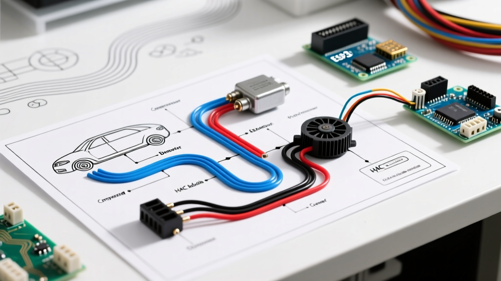

Mastering the Thermostat Wiring Diagram for Heat Pump Systems
Wiring a heat pump requires significantly more precision than a standard air conditioning or gas furnace setup. Unlike conventional systems that rely on a single-stage cooling or heating mechanism, a heat pump utilizes a reversing valve to switch refrigerant flow, alongside auxiliary electric heat strips for extreme cold snaps. If you are upgrading to a modern smart thermostat or replacing a damaged control board, understanding the exact thermostat wiring diagram for heat pump configurations is critical to prevent short-cycling, compressor damage, or blown 24VAC fuses.
In this comprehensive 2026 walkthrough, we break down the terminal matrix, the infamous O/B reversing valve conundrum, and the step-by-step physical wiring process for both legacy 18/8 setups and modern smart ecosystems like the Ecobee SmartThermostat Premium and the Nest Learning Thermostat (4th Gen).
Pre-Wiring Safety and Essential Tooling
Before touching a single terminal, you must eliminate the risk of electrical shock and protect the low-voltage control board. A short between the R (24VAC hot) and C (Common) wires will instantly blow the 3-amp or 5-amp automotive-style fuse on your air handler's control board, or worse, fry the transformer.
- Power Shutoff: Flip the breakers for BOTH the outdoor condenser unit and the indoor air handler at your main electrical panel. Verify the air handler is dead using a non-contact voltage tester.
- Wire Gauge: Ensure you are using 18 AWG, 8-conductor (18/8) thermostat wire. While 20/5 wire was common in the 1990s, modern heat pumps require the extra conductors for the C-wire (Common) and W2/AUX (Auxiliary Heat).
- Tools Required: Wire strippers (set to 18 AWG), a digital multimeter, a 1/4-inch nut driver, and a level for the thermostat baseplate.
The Heat Pump Terminal Matrix
Heat pump wiring relies on a standardized color code, though legacy installations may deviate. Below is the definitive terminal mapping for a standard single-stage heat pump with auxiliary heat.
| Terminal | Standard Wire Color | Function & System Role |
|---|---|---|
| R / Rc / Rh | Red | 24VAC Power from the transformer. Rc is for cooling, Rh for heating; most heat pumps use a single R jumpered to both. |
| Y / Y1 | Yellow | Compressor Contactor. Energizes the outdoor unit for the primary cooling or heating cycle. |
| W / W1 | White | Auxiliary Heat. Triggers the indoor electric heat strips when the heat pump cannot meet the thermostat's demand. |
| O / B | Orange or Blue | Reversing Valve. Dictates whether the system defaults to heating or cooling. (See O/B Conundrum below). |
| G | Green | Indoor Blower Fan. Energizes the air handler fan independently of the compressor. |
| C | Blue or Black | Common Wire. Completes the 24VAC circuit, providing continuous power for smart thermostat Wi-Fi radios and displays. |
| E | Emergency (Varies) | Emergency Heat. Bypasses the outdoor heat pump entirely, running only the indoor electric heat strips. |
The O/B Reversing Valve Conundrum
The most common failure point in heat pump wiring is misconfiguring the reversing valve terminal. The reversing valve physically shifts the flow of refrigerant to change the system from heating to cooling. However, manufacturers disagree on when this valve should be energized:
- Energize on Cool (O Terminal): Used by Rheem, Ruud, Lennox, and Goodman. The valve is spring-loaded to default to Heating. Power is applied to the O terminal to pull the valve into Cooling mode.
- Energize on Heat (B Terminal): Used almost exclusively by Trane, American Standard, and some older Carrier models. The valve defaults to Cooling. Power is applied to the B terminal to shift it into Heating mode.
Pro Tip: If you wire a Rheem system to the B terminal (or configure a smart thermostat to 'B' logic instead of 'O'), your heat pump will blow cold air in the dead of winter and hot air in the summer. Always verify the manufacturer's schematic on the inside of the air handler access panel.
Step-by-Step Wiring Walkthrough
Follow these sequential steps to terminate your thermostat wiring diagram for heat pump systems safely and accurately.
Step 1: Document and Remove the Legacy Thermostat
Before disconnecting any wires, take a high-resolution photo of the existing thermostat's terminal block. If the previous installer ignored standard color codes (e.g., using a green wire for the Y1 compressor terminal), your photo will be the only way to map the physical wires to the air handler's control board.
Step 2: Route and Prep the 18/8 Wire
Strip exactly 3/8 of an inch of insulation from each conductor. Stripping too much leaves exposed copper that can arc against adjacent terminals; stripping too little results in the terminal screw clamping onto the plastic insulation, causing an open circuit and a dead thermostat.
Step 3: Terminate the Air Handler Control Board
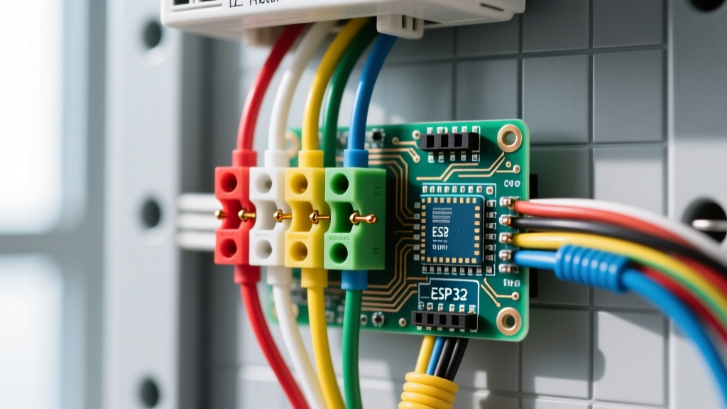
Open the indoor air handler panel and locate the low-voltage terminal strip. Connect the wires to their corresponding labels: R to R/24V, Y to Y, W to W1/AUX, G to G, C to C, and the reversing valve wire to O or B depending on your brand. Ensure the stranded copper is fully seated under the screw head and give each wire a gentle tug test.
Step 4: Mount and Wire the Thermostat Baseplate
Feed the 18/8 bundle through the new thermostat baseplate. Use a bubble level to ensure the plate is perfectly plumb; an unlevel baseplate can cause inaccuracies in older mercury-switch thermostats and can skew the ambient temperature readings on modern digital units due to internal heat rising unevenly across the PCB. Terminate the wires into the new baseplate matching the control board mapping.
Step 5: Configure the Smart Thermostat Software
Snap the smart thermostat onto the base and restore power at the breaker panel. The unit will boot and prompt you for the system type. Select Heat Pump, specify 1-Stage Compressor, 1-Stage Auxiliary Heat, and critically, select the correct O/B Reversing Valve logic based on your outdoor unit's brand.
2026 Smart Thermostat Upgrades and the C-Wire
As of 2026, the market is dominated by advanced smart thermostats that utilize AI-driven predictive algorithms to minimize auxiliary heat usage, which is the primary driver of high winter electric bills. Models like the Ecobee SmartThermostat Premium ($249) and the Nest Learning Thermostat 4th Gen ($279) require a dedicated C-wire to power their high-resolution displays, occupancy radar sensors, and continuous Wi-Fi connections.
According to the U.S. Department of Energy, properly configured smart thermostats can save homeowners up to 10% to 15% on heating and cooling costs annually by optimizing the heat pump's defrost cycles and auxiliary heat lockout temperatures. If your home lacks a C-wire, do not attempt to 'power steal' from the W or Y terminals, as this can cause the heat pump contactor to chatter or fail to engage. Instead, install a 24VAC Power Extender Kit (PEK) at the air handler control board to synthesize a common signal over the existing wires.
Troubleshooting Common Heat Pump Wiring Failure Modes
Even with a perfect physical termination, software configuration errors can mimic wiring faults. Use this diagnostic matrix to resolve common edge cases:
- Blowing Cold Air in Heat Mode: The O/B reversing valve logic is inverted in the thermostat's installer setup menu. Switch from O to B (or vice versa) and run a manual test cycle.
- Auxiliary Heat Running Constantly: The W1 terminal is shorted to R, or the thermostat's 'Compressor to Aux Run Time' delta is set too aggressively. Set the auxiliary lockout temperature to 35°F and the compressor-to-aux differential to 3°F to allow the heat pump time to satisfy the load before engaging the expensive electric strips.
- Outdoor Unit Won't Turn On (No Click at Contactor): Use a multimeter to check for 24VAC between the Y and C terminals at the outdoor contactor coil. If voltage is present but the coil doesn't pull in, the contactor is mechanically failed. If no voltage is present, trace the Y wire back to the air handler for a broken splice or a tripped high-pressure switch.
- Short Cycling on Y1: Often caused by a missing or loose G-wire connection at the air handler, preventing adequate indoor airflow, which triggers the coil freeze stat or high-head pressure switch to drop the Y1 circuit.
Final Verification and System Commissioning
Once wiring is complete, run a full 15-minute test cycle in Cooling, Heating, and Auxiliary Heat modes. Verify that the outdoor fan and compressor engage simultaneously with the indoor blower. For deeper insights into optimizing your system's efficiency ratings, refer to the EPA Energy Star Thermostat Guidelines, which detail the advanced setup parameters required to maintain SEER2 and HSPF2 compliance in modern variable-speed heat pumps. By meticulously following this thermostat wiring diagram for heat pump systems, you ensure maximum comfort, equipment longevity, and energy efficiency for years to come.