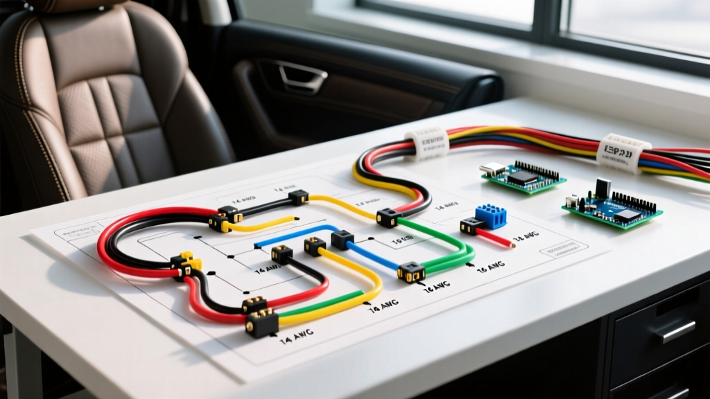

Decoding the Electric Seat Wiring Diagram
Upgrading, swapping, or repairing power seats requires more than just plugging in a connector. A modern 8-way or 10-way power seat assembly contains multiple high-draw DC motors, heating elements, memory modules, and occupant classification sensors. When interpreting or creating an electric seat wiring diagram, the most critical factor is managing the substantial current load without inducing voltage drop or creating a fire hazard. Unlike standard lighting circuits, seat motors experience massive inrush currents and stall conditions that demand precise wire gauge selection and high-temperature insulation.
This comprehensive reference guide breaks down the anatomy of power seat circuits, provides exact wire gauge specifications based on SAE J1128 automotive standards, and outlines the color-coding conventions necessary to avoid catastrophic interference with your vehicle's Supplemental Restraint System (SRS).
Anatomy of a Power Seat Circuit
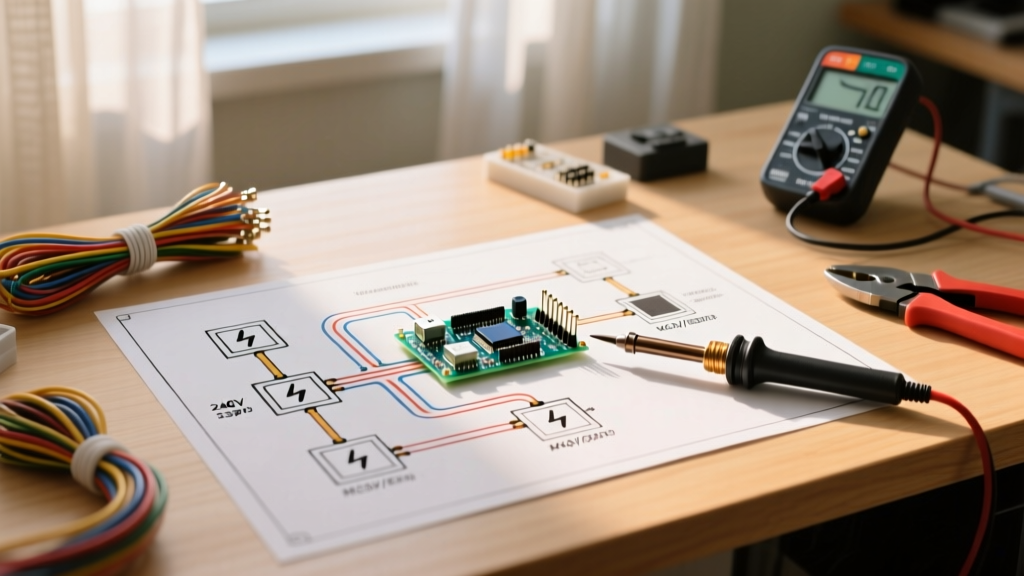
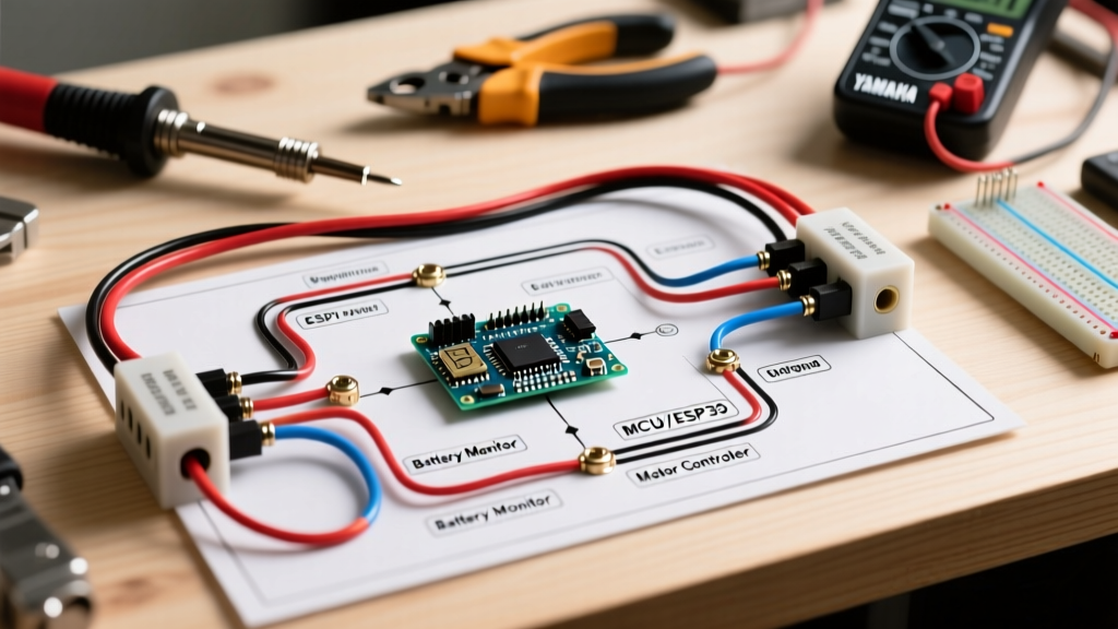
Before selecting wire, you must understand the load distribution across the seat harness. A typical OEM electric seat wiring diagram divides the circuit into three distinct sub-systems:
- High-Current Drive Motors: Slide, recline, front lift, and rear lift motors. These draw 10A to 15A continuously, with stall currents peaking at 25A to 30A.
- Thermal Loads: Seat heaters (and increasingly, ventilated seat blower motors). Heating elements draw 10A to 15A and require high-temperature wire insulation.
- Low-Current Logic & Sensors: Memory seat modules, lumbar bladders, CAN-bus communication lines, and occupancy sensors. These draw less than 2A but are highly sensitive to electromagnetic interference (EMI).
Wire Gauge Selection Matrix
Using standard household wire or undersized automotive primary wire is a leading cause of melted connectors and seat failure. Automotive environments require Thin Wall Cross-Linked (TXL) or General Cross-Linked (GXL) wire, which withstands under-dash temperatures up to 125°C (257°F) and resists abrasion. According to baseline ampacity guidelines outlined in NFPA 70 (NEC) and adapted for 12V DC automotive applications, use the following matrix for your harness build:
| Circuit Function | Recommended Gauge | Max Continuous Ampacity | Insulation Type | Connector Type |
|---|---|---|---|---|
| Main Power Feed (Battery to Seat) | 10 AWG | 30A | TXL / GXL | Deutsch DT / MaxiFuse |
| Main Ground (Seat to Chassis) | 10 AWG | 30A | TXL / GXL | Ring Terminal (1/4" stud) |
| Individual Motor Feeds (Slide/Recline) | 12 AWG | 20A | TXL | Metri-Pack 280 |
| Seat Heater Elements | 12 AWG | 20A | GXL (High Temp) | Metri-Pack 280 |
| Memory Module / Logic CAN-Bus | 18 AWG | 5A | TXL (Shielded) | Metri-Pack 150 |
Calculating Voltage Drop in Seat Harnesses
Power seats are notorious for operating sluggishly when voltage drops below 11.5V under load. If you are routing a main power feed from the engine bay fuse box through the firewall and down the rocker panel to the B-pillar, wire length becomes a critical variable.
Use the standard DC voltage drop formula: VD = (2 x K x I x L) / CM
- K = Copper resistivity constant (approx. 12.9 for 12V systems at operating temp)
- I = Current in Amps (e.g., 25A for simultaneous motor operation)
- L = One-way wire length in feet (e.g., 12 ft)
- CM = Circular mils of the wire (12 AWG = 6,530 CM; 10 AWG = 10,380 CM)
Example: Running 25A through 12 feet of 12 AWG wire yields a voltage drop of 1.18V. If your alternator is outputting 13.8V, the seat receives 12.62V, which is acceptable. However, if you use 14 AWG wire (4,110 CM), the drop increases to 1.88V, starving the motors and causing premature relay failure. Always default to 10 AWG for the main trunk line.
Automotive Wire Color Code Standards
While aftermarket harness builders often use whatever spool is on the bench, OEM electric seat wiring diagrams adhere to strict color-coding conventions to prevent cross-circuit shorts. When repairing or extending a factory harness, match these industry-standard colors (based on DIN 72551 and SAE conventions):
- Red / Red-White: Unswitched Battery Power (B+). Direct from the fuse panel.
- Black / Brown: Main Chassis Ground. Must be tied to a bare-metal B-pillar or floor pan grounding stud.
- Yellow / Yellow-Black: Switched Ignition Power (ACC/IGN). Used for memory module wake-up and seat heater logic.
- Blue / Green: Motor control polarity reversal lines. (e.g., Light Blue for Slide Forward, Dark Blue for Slide Rearward).
- Orange / Purple: CAN-High and CAN-Low data lines for memory seat networking.
CRITICAL SRS WARNING: If you encounter Bright Yellow or Orange connectors and wiring under the seat, STOP immediately. These are dedicated Supplemental Restraint System (SRS) circuits for side-impact airbags and seatbelt pretensioners. Never probe these circuits with a standard multimeter, as the internal battery in the meter can provide enough current to inadvertently deploy the pyrotechnic pretensioner or trigger the airbag module. Always disconnect the vehicle's main battery and wait 15 minutes for the SRS capacitor to discharge before working near yellow harnesses.
Common Failure Modes & Edge Cases
When troubleshooting an existing electric seat wiring diagram, 80% of electrical failures stem from physical harness degradation rather than motor burnout. Look for these specific edge cases:
1. The 'Under-Seat Chafe' Short
Drivers frequently shove water bottles, flashlights, or umbrellas under the seat. When the seat adjusts, these objects are driven into the wiring loom, piercing the insulation and shorting the 12V motor feeds to the grounded steel seat track. Fix: Replace damaged wires and wrap the entire under-seat loom in Tesa 51036 PET cloth tape. This specific abrasion-resistant tape is the OEM standard for protecting harnesses in high-friction zones.
2. Seat Track Pinch Points
Improperly routed harnesses get caught in the scissor-lift mechanisms or slide tracks. As the seat moves forward, the wire stretches; as it moves back, it gets crushed. Fix: Implement a 'service loop.' Leave exactly 4 to 6 inches of slack in the harness directly beneath the seat pan, secured with a plastic fir-tree push clip to the floor pan, ensuring the wire moves in a gentle 'S' curve rather than a tight pivot.
3. Memory Module CAN-Bus Interference
If your memory seat functions erratically (e.g., moving when the car is off, or failing to save positions), the unshielded CAN-bus wires may be picking up EMI from the high-current seat heater PWM (Pulse Width Modulation) circuit. Fix: Reroute the 18 AWG logic wires away from the 12 AWG heater feeds, or upgrade the logic wires to shielded twisted-pair (STP) automotive cable, grounding the shield drain wire at the module end only.
Step-by-Step Harness Routing Best Practices
- Fuse Placement: Install a 30A MaxiFuse or MIDI fuse within 8 inches of the battery positive terminal. Do not rely solely on the interior fuse box for main feed protection.
- Firewall Pass-Through: Never drill a new hole through the firewall. Locate the main body control module (BCM) grommet, use a plastic trim pick to create a slit, and feed the 10 AWG TXL wire through, sealing it with dielectric grease.
- Grounding: Sand the B-pillar ground point down to bare, shiny metal. Use a 10 AWG closed-loop ring terminal, secure it with an M6 or M8 flange nut, and coat the connection with battery terminal protector spray to prevent galvanic corrosion.
- Connector Seating: When using Metri-Pack or Deutsch connectors, always perform a 'pull test.' Tug firmly on the wire after crimping and inserting the pin into the housing to ensure the secondary lock (TPA) is fully engaged.
Summary
Building or repairing an electric seat wiring diagram requires respecting the high-current demands of DC motors and the delicate nature of modern vehicle networking. By adhering to 10 AWG and 12 AWG TXL specifications, utilizing proper service loops, and strictly avoiding SRS yellow-harness zones, you ensure a reliable, fire-safe power seat installation that will withstand years of daily adjustment and thermal cycling.