
Mastering the Wiring Diagram for Sunpro Tachometer Installations
Installing an aftermarket tachometer is a rite of passage for gearheads, hot rodders, and classic car restorers. Among the most popular and accessible gauge brands on the market is Sunpro, a subsidiary of AutoMeter. Whether you are dropping a 3-3/8-inch Sunpro CP7905 into a custom dashboard or mounting a pedestal tachometer on your steering column, understanding the exact electrical requirements is critical. A poorly wired tachometer will result in bouncing needles, inaccurate RPM readings, or a completely dead gauge. This comprehensive motor wiring tutorial breaks down the exact wiring diagram for Sunpro tachometer models, covering wire color codes, ignition signal routing, and advanced troubleshooting for modern engine swaps.
Deconstructing the Sunpro 4-Wire Harness
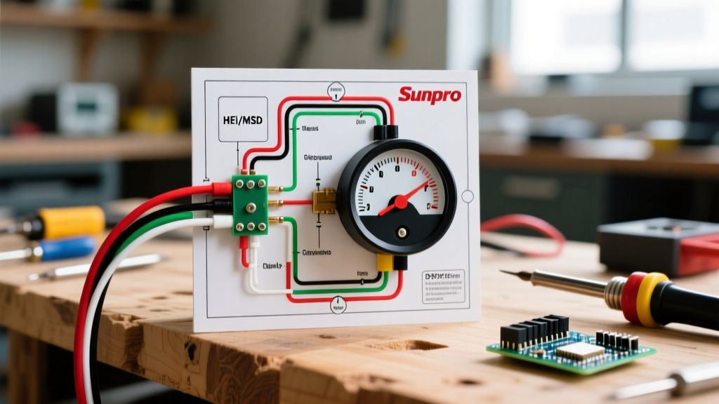
Unlike complex digital gauge clusters that rely on CAN-bus networks, standard analog Sunpro tachometers utilize a straightforward 4-wire harness. Misidentifying these wires is the most common cause of installation failure. Below is the definitive breakdown of the Sunpro wiring color code:
- Red Wire (Switched 12V Power): This wire must be connected to a 12-volt source that is only active when the ignition key is in the "ON" or "START" position. Connecting this to a constant 12V battery source will drain your battery and leave the gauge illuminated when the car is off.
- Black Wire (Chassis Ground): This provides the return path for the electrical circuit. It must be grounded to a clean, bare metal surface on the chassis or engine block. Do not simply wrap it around a bolt; use a ring terminal and secure it to unpainted metal.
- Green Wire (Tachometer Signal): This is the most critical and misunderstood wire. It reads the voltage pulses from your ignition system to calculate RPM. The connection point changes drastically depending on whether you are running a points distributor, an HEI system, or an aftermarket CDI box.
- White Wire (Illumination): This wire powers the internal dial light. It should be spliced into your vehicle's headlight switch or dashboard illumination circuit so the gauge dims or turns on with your other instrument lights.
Wire Gauge and SAE Standards
When extending the Sunpro harness through the firewall, you must adhere to proper automotive wire standards. According to the SAE J1128 Low Tension Primary Cable Standard, 18 AWG (American Wire Gauge) stranded copper wire is the optimal choice for gauge circuits drawing less than 5 amps. Using wire that is too thick makes routing difficult, while wire that is too thin can introduce voltage drop, causing the internal lighting to flicker or the gauge motor to behave erratically.
Step-by-Step Wiring Instructions
Before cutting or splicing any wires, disconnect the negative terminal on your vehicle's battery to prevent accidental short circuits. Gather your tools: a quality wire stripper, a soldering iron, heat shrink tubing, and a digital multimeter.
- Route the Harness: Feed the Sunpro wiring harness through the firewall using an existing rubber grommet. Never pass wires through bare metal, as engine vibration will eventually strip the insulation and cause a dead short.
- Connect the Ground (Black): Crimp a ring terminal onto the black wire. Locate a solid grounding point on the dashboard frame or steering column support. Sand away any paint or powder coating to ensure bare metal contact, then secure the bolt tightly.
- Connect the Power (Red): Use your multimeter to probe the fuse box. Find a circuit that reads 0V with the key off, and 12V with the key on (e.g., the radio or wiper fuse). Use an add-a-circuit fuse tap to connect the red wire. Ensure the tap is fused at 5A or 10A to protect the gauge.
- Connect the Illumination (White): Locate the dashboard lighting wire (often brown or blue, depending on the vehicle manufacturer). Splice the white wire into this circuit using a soldered connection sealed with adhesive-lined heat shrink.
- Connect the Signal (Green): Route the green wire to the engine bay. The destination of this wire depends entirely on your ignition system (detailed in the next section).
Ignition System Signal Routing: Where Does the Green Wire Go?
The green signal wire requires a specific type of electrical pulse to function. Sending the wrong signal will instantly destroy the internal circuitry of the tachometer. Consult the AutoMeter Technical Resources database for specific ignition compatibilities, but generally, follow these rules based on your motor setup:
1. Standard Points or Breakerless Distributors
For classic V8s and older inline engines using standard ignition coils, the green wire connects directly to the negative terminal of the ignition coil. The points or internal pickup module ground and unground this terminal, creating a 12V square wave pulse that the tachometer reads.
2. GM HEI (High Energy Ignition) Distributors
If your motor is equipped with a GM HEI distributor, do not connect the green wire to the coil. Instead, look for a dedicated terminal on the distributor cap labeled "TACH". This terminal provides a clean, buffered 12V pulse specifically designed for aftermarket gauges.
3. Aftermarket CDI Boxes (MSD 6AL, 6010, etc.)
Capacitive Discharge Ignition (CDI) systems fire the coil with massive voltage spikes (up to 400V+). Connecting a standard Sunpro tachometer directly to the coil negative terminal on an MSD-equipped car will fry the gauge. You must connect the green wire to the dedicated Tach Output wire on the CDI box (usually a white or brown wire on MSD units). If your CDI box does not have a dedicated tach output, you must install an MSD 8910 Tach Adapter between the coil and the gauge.
4. Modern LS-Swaps and EFI Engines
Modern engine control modules (ECMs) output a 5V square wave tach signal from the PCM. Most standard analog Sunpro tachometers expect a 12V pulse. To bridge this gap, you will need to use a signal pull-up resistor or a dedicated tach interface module (like the Dakota Digital SGI-5E) to convert the 5V PCM signal to a 12V signal the Sunpro gauge can read.
Signal and Wiring Reference Matrix
| Wire Color | Function | Connection Point | Multimeter Test (Key ON) |
|---|---|---|---|
| Red | Switched Power | Fuse Box (Ignition Circuit) | 12.0V - 12.6V |
| Black | Chassis Ground | Bare Metal Dashboard Frame | 0.0V (Continuity to Battery -) |
| Green | Tach Signal | Coil (-), HEI Tach, or CDI Output | Pulsing Voltage (Engine Cranking) |
| White | Illumination | Headlight Switch / Dash Lights | 12V (Lights ON) / 0V (Lights OFF) |
Cylinder Calibration: The Hidden Step
Even with perfect wiring, your Sunpro tachometer will display incorrect RPMs if the cylinder calibration is wrong. Tachometers calculate RPM by counting the number of ignition pulses per crankshaft revolution. A 4-cylinder engine fires twice per revolution, a 6-cylinder fires three times, and an 8-cylinder fires four times.
On the back of the Sunpro gauge housing, you will find either a small rotary dial or a set of dip-switches. Before mounting the gauge into the dashboard or cup, use a small flathead screwdriver to set this switch to match your engine's cylinder count. If you install an 8-cylinder tachometer on a 4-cylinder engine without adjusting the switch, the needle will read exactly double the actual RPM (e.g., showing 4,000 RPM when the engine is actually idling at 2,000 RPM).
Advanced Troubleshooting and Failure Modes
If you have followed the wiring diagram for your Sunpro tachometer and the gauge is still misbehaving, use this diagnostic framework to isolate the failure mode:
The Needle Bounces Wildly at High RPM
Cause: Electromagnetic Interference (EMI). The green signal wire is picking up noise from high-tension spark plug wires or alternator whine.
Solution: Reroute the green tachometer signal wire so it is at least 4 inches away from any spark plug wires, ignition coils, or high-amperage alternator cables. If the bouncing persists, install a 0.01µF ceramic capacitor between the green signal wire and the black ground wire near the gauge to filter out high-frequency noise.
The Needle Pegs at Maximum RPM and Stays There
Cause: The green signal wire is shorted to ground, or you are feeding an incompatible signal (such as a raw 400V coil pulse from an MSD box into a standard gauge).
Solution: Disconnect the green wire from the engine bay. If the needle drops to zero, the issue is under the hood (check for a pinched wire or incorrect CDI connection). If the needle stays pegged with the green wire disconnected, the internal gauge circuitry has likely been destroyed by a voltage spike and the unit must be replaced.
The Needle Reads Exactly Half or Double the Actual Speed
Cause: Incorrect cylinder calibration.
Solution: Remove the gauge from its mount and verify the dip-switch or rotary dial on the back. Adjust it to match the exact cylinder count of your motor. Note that some odd-fire V6 or rotary engines require specialized tachometers; a standard Sunpro tach will not read odd-fire patterns correctly.
The Gauge is Completely Dead (No Light, No Needle Movement)
Cause: Loss of power or ground.
Solution: Use a multimeter to check for 12V between the red wire and the black wire at the gauge connector. If you read 0V, check your fuse tap and ignition switch. If you read 12V but the gauge is dead, test the black wire for continuity to the battery negative terminal. A painted or rusty ground point is the culprit in 90% of "dead gauge" scenarios.
Pro-Tip for Engine Swaps: When performing an LS or Coyote engine swap into a classic chassis, always bench-test the Sunpro tachometer using a dedicated signal generator or by temporarily wiring it to the donor engine's PCM before routing the harness through the firewall. This saves hours of troubleshooting if the 5V-to-12V signal converter is defective.
Final Assembly and Safety Checks
Once all wiring is verified and the cylinder count is set, secure the gauge into its mounting cup or dashboard bezel. Reconnect the vehicle's battery and turn the key to the "ON" position. The needle should sweep to the calibration mark (usually 1,000 or 1,500 RPM) and then settle at zero. Start the engine and verify that the idle RPM matches your known baseline. By strictly adhering to this wiring diagram and respecting the nuances of your specific ignition system, your Sunpro tachometer will provide reliable, accurate telemetry for every mile ahead.