
Decoding the Wiring Diagram for RV Trailer Electrical Panels
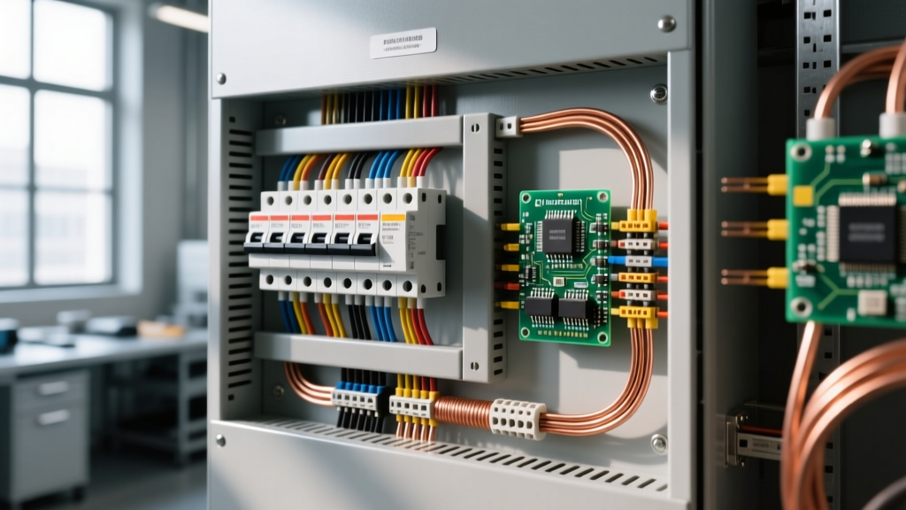
Understanding the complete wiring diagram for RV trailer setups is the difference between a reliable off-grid experience and a catastrophic electrical fire. Unlike residential homes, recreational vehicles operate on a complex dual-voltage architecture. You are essentially managing a 120V AC shore-power grid and a 12V DC battery network within a single, vibration-prone metal chassis. When you examine the schematic of any modern travel trailer or fifth wheel, the central nervous system is the AC/DC distribution panel. This guide breaks down the panel wiring topology, breaker sizing matrices, and critical routing specifications required for safe, code-compliant installations in 2026.
The Dual-Voltage Architecture
Every standard RV wiring diagram splits into two distinct halves at the distribution center. The AC side receives 30-amp or 50-amp service from a campground pedestal or generator, routing it through a main disconnect breaker before feeding branch circuits (air conditioning, microwave, outlets). Simultaneously, the AC side powers an integrated converter/charger. This converter steps down 120V AC to 13.6V DC, feeding the DC fuse board to power lights, water pumps, and slide-out motors, while simultaneously charging the house battery bank. The physical separation of these bus bars inside the panel is mandated by NFPA 70 (National Electrical Code) Article 551, which governs recreational vehicle electrical safety.
Core Components in Modern RV Distribution Panels
When planning your trailer's electrical layout, you will typically choose between two industry-standard panel configurations. Both integrate the AC breakers, DC fuses, and power converter into a single wall-mounted chassis.
- Progressive Dynamics PD4151 (or PD4151L for Lithium): Priced around $175-$195 in 2026, this 50-amp AC / 55-amp DC unit is the gold standard for DIY trailer builds. The 'L' variant features a proprietary charge profile specifically mapped for LiFePO4 batteries, eliminating the need for external BMS chargers.
- WFCO WF-8955: A slightly more budget-friendly option ($130-$150), offering 50A AC and 55A DC. While reliable, older WFCO models were notorious for failing to drop into the 14.4V absorption phase required to fully charge AGM or Lithium batteries, though their newer 2025/2026 'ADV' series has largely resolved this with auto-detect circuitry.
Breaker and Fuse Sizing Matrix
A common error when interpreting a wiring diagram for RV trailer builds is over-fusing a circuit to prevent nuisance trips. This defeats the purpose of the overcurrent protection device (OCPD) and risks melting the wire insulation. Use the matrix below to match your loads, wire gauges, and breaker sizes.
| Appliance / Load | Voltage | Wire Gauge (THHN/Stranded) | OCPD Size (Breaker/Fuse) |
|---|---|---|---|
| Main AC Shore Power (30A Service) | 120V AC | 10 AWG | 30A Double-Pole (Main) |
| Roof Air Conditioner (15k BTU) | 120V AC | 12 AWG | 20A Single-Pole |
| Microwave / GFCI Receptacles | 120V AC | 12 AWG | 20A Single-Pole |
| Water Heater (Electric Element) | 120V AC | 14 AWG | 15A Single-Pole |
| Slide-Out Motors (Hydraulic/Elec) | 12V DC | 6 AWG | 30A Blade Fuse (DC Bus) |
| Water Pump & 12V Fridge Logic | 12V DC | 12 AWG | 15A ATC Blade Fuse |
| LED Interior Lighting | 12V DC | 14 AWG or 16 AWG | 10A ATC Blade Fuse |
Step-by-Step Panel Wiring & Routing Guide
Executing the physical wiring requires strict adherence to torque specifications and bend radius limits. According to RV industry experts featured on RVtravel.com, loose neutral connections are the leading cause of RV electrical fires.
1. AC Shore Power Routing
Route your 10 AWG shore power cord through a liquid-tight strain relief connector into the panel's AC knock-out. Strip exactly 1/2 inch of insulation. Connect the Black (Hot) to the main 30A breaker, the White (Neutral) to the isolated AC neutral bus bar, and the Green (Ground) to the chassis-grounded AC ground bus bar. Torque all AC terminal screws to 20-25 in-lbs.
2. DC Converter & Battery Integration
The converter outputs 12V DC via heavy-gauge wires. For a 55A converter, use 6 AWG stranded copper wire for the run to the battery bank if the distance exceeds 10 feet to mitigate voltage drop. Install a 60A Class T fuse or ANL fuse within 18 inches of the battery positive terminal. The DC negative must route back to the panel's DC negative bus bar, which is bonded to the RV chassis ground.
3. Branch Circuit Dressing
Use nylon cable ties every 8 inches to dress the wires. Keep 120V AC wires physically separated from 12V DC wires by at least 2 inches where possible to prevent electromagnetic interference (EMI), which can cause flickering in sensitive LED lighting circuits.
2026 Lithium Converter Upgrades & Edge Cases
If you are upgrading an older trailer to a Lithium Iron Phosphate (LiFePO4) battery bank, the standard wiring diagram must be modified. Standard lead-acid converters output a fixed 13.6V, which will only charge a lithium battery to roughly 85% capacity and will eventually trigger the battery's internal BMS low-voltage disconnect.
Pro Tip: When retrofitting a Progressive Dynamics panel for lithium, you do not need to replace the entire metal chassis. You can purchase the PD4151L replacement converter section (approx. $110) and slide it into the existing PD4100 series shell, instantly upgrading your DC charge profile to a 14.6V bulk/absorption curve.
Common Failure Modes & Troubleshooting
Even with a perfect schematic, real-world trailer environments introduce vibration, moisture, and thermal cycling. Watch for these specific edge cases:
- Neutral-to-Ground Bonding Errors: In an RV, the neutral and ground must only be bonded at the source (the campground pedestal or the onboard generator). They must remain strictly isolated inside the trailer's distribution panel. If a DIYer incorrectly bonds them at the panel, return current will travel along the chassis ground, creating a lethal shock hazard if the skin of the trailer becomes energized.
- Converter Ripple Current: Failing converter capacitors introduce AC 'ripple' into the 12V DC line. This manifests as a 60Hz hum in audio equipment or premature failure of 12V compressor fridge control boards. Test DC voltage with a multimeter set to AC Volts; if you read more than 0.5V AC on the DC bus, the converter requires immediate replacement.
- Thermal Creep on DC Fuses: High-draw DC loads like 12V compressor fridges or inverters generate heat. Over time, this heat causes the tin plating on automotive ATC blade fuses to oxidize and 'creep,' increasing resistance. Inspect and reseat all DC blade fuses annually, and upgrade high-draw circuits to bolt-on Mega or Class T fuses.
Final Safety Verification
Before energizing the system, use a digital multimeter to verify continuity between the shore power ground pin and the RV chassis (should be less than 0.5 ohms). Verify infinite resistance (OL) between the AC Hot and AC Neutral, and AC Hot and Ground, ensuring no dead shorts exist in your branch wiring. For comprehensive safety standards and inspection checklists, always refer to the Progressive Dynamics technical support documentation and local electrical codes before finalizing your build.