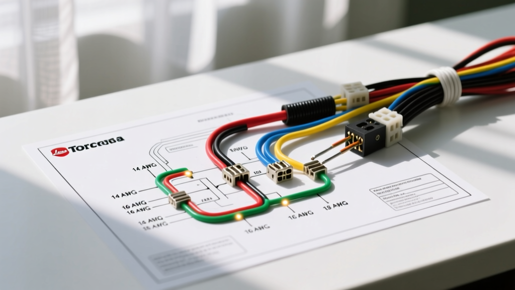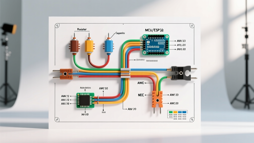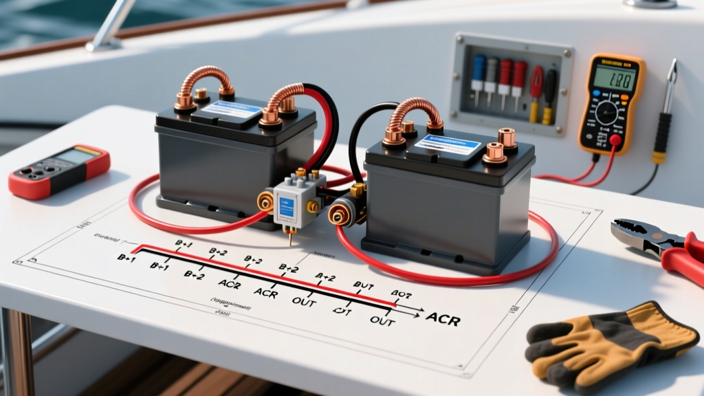

The Complete Dual Battery Wiring Diagram for Boat Applications
Upgrading to a dual-battery marine system is one of the most impactful modifications you can make to your vessel. Whether you are powering a 36-pound thrust Minn Kota trolling motor, running a live well pump, or keeping a 12V Dometic marine fridge cold overnight, separating your starting (cranking) battery from your house (accessory) bank ensures you will never be stranded on the water. However, executing a reliable dual battery wiring diagram for boat configurations requires strict adherence to marine-grade standards, proper wire gauging, and an understanding of modern battery chemistries.
In this 2026 comprehensive walkthrough, we will guide you through the exact steps to wire a dual-battery system using an Automatic Charging Relay (ACR) for traditional AGM/Lead-Acid setups, while also addressing the critical nuances of integrating Lithium Iron Phosphate (LiFePO4) house banks.
Core System Architecture: ACR vs. DC-DC Chargers
Before cutting any wire, you must select the correct battery isolation and charging management device. The choice depends entirely on your battery chemistry.
Scenario A: Matched Chemistries (AGM to AGM or Lead-Acid to Lead-Acid)
For identical battery types, an Automatic Charging Relay (ACR) or Voltage Sensitive Relay (VSR) is the industry standard. When your outboard alternator raises the starting battery voltage to a threshold (typically 13.0V to 13.6V), the ACR closes, combining the banks to charge both simultaneously. When the engine stops and voltage drops below 12.35V, the ACR opens, isolating the house bank so your accessories cannot drain your cranking battery. The Blue Sea Systems 7650 ACR (retailing around $95-$110) remains the gold standard for this application due to its ignition port isolation and robust 120A continuous rating.
Scenario B: Mixed Chemistries (Lead-Acid Start + LiFePO4 House)
If you are running a LiFePO4 house bank in 2026, do not use a standard ACR. Lithium batteries have incredibly low internal resistance and can draw massive, unregulated current from your alternator, potentially melting wiring or triggering the lithium Battery Management System (BMS) to abruptly open. A sudden BMS disconnect with an ACR can cause a massive voltage spike, destroying your alternator diodes. Instead, you must use a smart DC-DC battery charger, such as the Victron Energy Orion XS 12/12-50A ($160-$190), which safely limits alternator current and provides the exact absorption/float profile required by lithium cells.
Wire Sizing and ABYC Compliance
Marine environments demand tinned, ultra-flexible copper wire (such as Ancor Marine Grade). Untinned wire will wick moisture via capillary action, turning green and failing within a single season. Sizing your wire correctly prevents voltage drop and fire hazards. According to the American Boat and Yacht Council (ABYC) E-11 standard, marine wire must be sized based on the maximum continuous amperage and the total round-trip circuit length (positive + negative wire) to maintain a voltage drop of less than 3% for critical electronics.
| Max Continuous Amps | Total Circuit Length (ft) | Minimum AWG Size (Tinned) | Typical Use Case |
|---|---|---|---|
| 50A | Up to 15 ft | 6 AWG | Windlass, small inverter |
| 100A | Up to 15 ft | 2 AWG | ACR main feed, large inverter |
| 150A | Up to 15 ft | 1/0 AWG | High-output alternator feed |
| 200A+ | Up to 15 ft | 2/0 AWG | Main battery bank interconnects |
Note: Always round up to the next available AWG size if your exact length or amperage falls between table values.
Step-by-Step Wiring Walkthrough
This walkthrough assumes a standard twin-battery layout using a Blue Sea 7650 ACR and matched AGM batteries. Gather your tools: a heavy-duty hex-crimp tool (not a hammer crimper), 3M FP-301 adhesive-lined heat shrink, a heat gun, and a multimeter.
Step 1: Overcurrent Protection Placement
ABYC standards dictate that overcurrent protection (fuses or circuit breakers) must be installed within 7 inches of the battery positive terminal. If the wire must pass through a bulkhead before the fuse, it must be enclosed in a protective sheath. For high-capacity AGM or Lithium banks, use Class T fuses (like the Blue Sea 5112 series) rather than standard ANL fuses. Class T fuses have a higher Ampere Interrupting Capacity (AIC) of 20,000 amps, which is critical for safely halting the massive fault currents modern marine batteries can deliver during a dead short.
Step 2: Routing and Securing the Main Feed
Run your 2 AWG positive and negative cables from Battery 1 (Starting) and Battery 2 (House) to a centralized busbar or the ACR location. Keep positive and negative runs separated by at least 2 inches where possible to prevent inductive interference and make future troubleshooting easier. Secure the cables every 18 inches using UV-resistant, stainless-steel cushion clamps. Never use standard zip-ties for primary battery feeds, as they become brittle and snap under engine vibration.
Step 3: Crimping and Terminating
Strip exactly 5/8-inch of insulation from your 2 AWG wire. Slide a piece of 3/8-inch adhesive-lined heat shrink over the wire before inserting the terminal. Insert the bare copper into a heavy-duty tinned copper ring terminal (e.g., Ancor 113525). Use a calibrated hex-crimp tool to compress the terminal. The adhesive-lined heat shrink must be shrunk with a heat gun until the inner adhesive oozes slightly out the back—this creates a watertight seal that prevents salt-air corrosion.
Step 4: Connecting the ACR
Mount the ACR in a dry, well-ventilated area away from direct engine heat. Connect the large positive stud (B1) to the Starting Battery positive bus, and the other large stud (B2) to the House Battery positive bus. Connect the ACR's negative ground wire to the main negative busbar. Crucial Detail: Connect the yellow ignition isolation wire to an ignition-run circuit. This prevents the ACR from combining the banks when the engine is off but the ignition key is left in the 'on' position, which would otherwise drain your starting battery via the house loads.
Step 5: Final Verification
Before connecting the final battery negative, double-check all torque specs. A loose 2 AWG terminal creates high resistance, generating extreme heat under load. Use a torque wrench set to the manufacturer's specification (typically 100-120 in-lbs for 5/16" terminal studs). Connect the negatives, turn on the house loads, and verify with a multimeter that the starting battery remains isolated at resting voltage (approx 12.6V) while the house bank drops slightly under load.
Pro-Tip for 2026 Marine Rigs: Install a Bluetooth-enabled battery monitor (like the Victron SmartShunt 500A) on the house bank's negative lead. This provides real-time state-of-charge data directly to your smartphone, eliminating the guesswork of analog voltmeters which are notoriously inaccurate for determining true battery capacity.
Common Failure Modes and Edge Cases
- Parasitic Draw via the ACR: If your ACR lacks an ignition isolation wire (or it is wired incorrectly), the relay's internal coil and the house bank's phantom loads can slowly drain the cranking battery over a multi-day mooring.
- Voltage Drop Masking: If you use undersized wire (e.g., 4 AWG instead of 2 AWG for a long run), the voltage drop across the wire may prevent the ACR from sensing the 13.0V threshold, causing it to never combine the banks. The house battery will slowly die while the engine runs.
- Galvanic Corrosion: Mixing stainless steel hardware with standard brass or copper terminals without using dielectric grease or tinned marine hardware will result in rapid galvanic corrosion in saltwater environments.
Final Thoughts
Executing a proper dual battery wiring diagram for boat applications is about much more than just connecting positive to positive. It requires a methodical approach to wire gauging, strict adherence to ABYC overcurrent placement rules, and an understanding of how modern battery chemistries interact with charging relays. By investing in tinned marine wire, Class T fusing, and high-quality adhesive heat shrink, you ensure your vessel's electrical system remains safe, reliable, and ready for the open water.