
Mastering the Wiring Diagram for Exhaust Fan Installations
Installing a bathroom ventilation system is one of the most critical electrical tasks in residential wiring. Improper moisture extraction leads to mold, while faulty wiring creates severe fire hazards. Whether you are upgrading to a premium ultra-quiet model like the Panasonic WhisperCeiling FV-0511VQ1 (retailing around $140-$160 in 2026) or installing a budget-friendly Broan-NuTone 505 ($65-$80), understanding the correct wiring diagram for exhaust fan setups is non-negotiable.
This comprehensive walkthrough breaks down the standard single-pole switch configuration, integrates modern National Electrical Code (NEC) requirements, and provides actionable troubleshooting data. We will focus on the most common residential scenario: running power from the electrical panel to the wall switch, and then sending a switched load up to the ceiling fan.
NEC Code Requirements & Safety Parameters
Before stripping a single wire, you must align your plan with the active 2023 NEC (widely enforced through 2026). According to the National Fire Protection Association (NFPA 70), specific rules govern bathroom ventilation circuits:
- NEC 210.11(C)(3): Bathroom receptacles must be on a dedicated 20-amp circuit. However, a hardwired exhaust fan can be on this same 20-amp circuit, provided the fan is not the sole load and the circuit does not supply outlets in other rooms.
- NEC 404.2(C) - The Neutral Requirement: Modern smart switches, humidity sensors, and timers require a neutral wire at the switch box. You must run a 3-wire cable (or standard 2-wire NM-B where white is re-identified) to ensure a grounded circuit conductor is present at the switch location.
- NEC 409.42 - GFCI Protection: If your exhaust fan is installed directly over a shower or bathtub zone, it must be GFCI protected and explicitly listed by the manufacturer for 'over-tub' use. If it is mounted on a dry ceiling outside the shower zone, standard circuit breaker protection suffices.
Safety Warning: Always verify power is completely de-energized using a non-contact voltage tester (like the Klein Tools NCVT-3, approx. $25) and a multimeter before touching any terminals. Never rely solely on a wall switch being in the 'off' position.
Materials & Wire Gauge Selection Matrix
Choosing the correct cable prevents voltage drop and ensures the breaker trips correctly during a short circuit. Most bathroom fans draw less than 1.5 amps, but the wire gauge is dictated by the circuit breaker protecting the line, not the fan's amperage.
| Circuit Breaker Size | Required NM-B Cable | Max Run Length (3% Drop) | Common Application |
|---|---|---|---|
| 15 Amp | 14/2 NM-B (Romex) | 50 feet | Lighting-only or dedicated fan circuits |
| 20 Amp | 12/2 NM-B (Romex) | 60 feet | Shared bathroom receptacle & fan circuits |
Note: If you are installing a fan/heater combo unit (like the Broan-NuTone 9093WH, which draws ~12.5 amps for the heater element), a dedicated 20-amp circuit with 12/2 NM-B is strictly required.
The Standard Wiring Diagram Explained
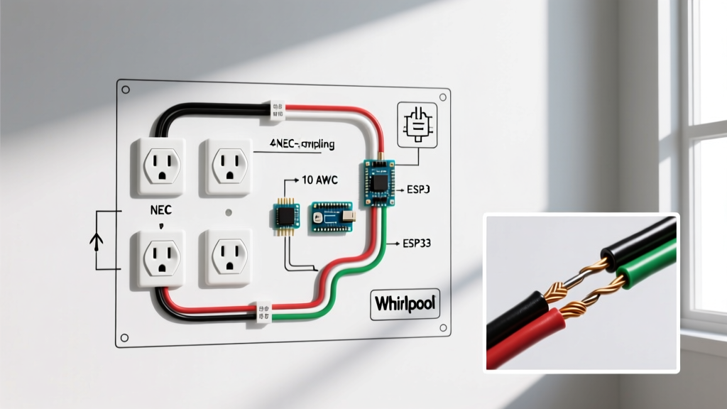
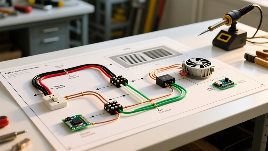
The standard wiring diagram for exhaust fan setups follows a logical path: Power Source → Wall Switch → Fan Motor.
- Line (Hot): Black wire from the panel enters the switch box.
- Switched Load: Black wire leaving the switch travels up to the fan canopy.
- Neutral: White wires are spliced together in the switch box (to satisfy NEC 404.2(C) for future smart switches) and travel continuously to the fan.
- Ground: Bare copper wires are bonded to the metal switch box, the switch ground screw, and the fan chassis.
Step-by-Step Wiring Walkthrough
Step 1: Rough-In and Cable Routing
Run your 12/2 or 14/2 NM-B cable from the wall switch location up through the top plate and into the ceiling joist bay where the fan housing will sit. Leave at least 12 inches of slack inside the fan's electrical knockout box and 8 inches inside the wall switch box. Secure the cable to the joists using approved cable staples within 8 inches of the boxes.
Step 2: Wiring the Wall Switch
For a standard single-pole toggle or a modern humidity-sensing switch (like the Leviton DHS05, approx. $45):
- Strip exactly 3/4 inch of insulation from the wire ends.
- Connect the incoming Line (Hot) black wire to the bottom brass terminal on the switch.
- Connect the outgoing Load black wire to the top brass terminal.
- Pigtail the two white neutral wires together with a yellow Ideal Wire-Nut and push them to the back of the box. (If using a smart timer/sensor, connect the switch's white neutral wire to this pigtail).
- Connect the bare ground wires to the green ground screw on the switch and the metal box.
Step 3: Wiring the Fan Canopy
Open the fan's integrated junction box. You will typically find three wire leads (Black, White, Green/Bare) or a plug-in receptacle inside the housing.
- Neutral Connection: Connect the white wire from the ceiling cable to the white wire on the fan motor using a wire nut. Tug gently to ensure a solid mechanical grip.
- Hot Connection: Connect the black wire from the ceiling cable (the switched load) to the black wire on the fan motor.
- Grounding: This is where many DIYers fail. Do not just wire-nut the ground wire. You must attach the bare copper ground wire to the dedicated green grounding screw located on the fan's metal junction box chassis, ensuring a continuous ground fault path back to the panel.
Advanced Configurations: Timers and Humidity Sensors
The EPA ENERGY STAR guidelines strongly recommend running exhaust fans for at least 20 minutes after a shower to fully evacuate moisture. Standard toggle switches fail at this because users forget to turn them off.
Upgrading to an electronic countdown timer (e.g., Lutron MA-T51H, $35) requires the neutral wire we preserved in Step 2. The wiring diagram shifts slightly: the Line and Load connect to the respective brass screws, but the switch's white neutral wire must now be integrated into the neutral pigtail bundle, and the switch's green ground connects to the ground bundle.
Troubleshooting Matrix: Common Failure Modes
If your installation is complete but the fan is misbehaving, use this diagnostic matrix before tearing open the ceiling.
| Symptom | Probable Cause | Diagnostic Fix |
|---|---|---|
| Fan hums but motor won't spin | Failed start capacitor or bound blower wheel | Check for physical obstruction. If clear, the internal capacitor on the motor board is blown; replace the motor assembly. |
| Breaker trips immediately upon switch-on | Pinched NM-B cable or shorted switch leg | Inspect where the cable enters the metal fan housing. Ensure the 3/8" Romex connector is seated and a wire wasn't sliced by the knockout edge. |
| Fan runs, but extremely loud/rattling | Housing not isolated from joist or loose blower wheel | Verify the hanger brackets are decoupled from the joists using the provided isolation pads. Tighten the blower wheel set-screw. |
| Smart timer switch won't power on | Missing or disconnected neutral at switch box | Verify the white neutral pigtail is securely connected to the switch's white lead. Smart switches cannot complete their internal logic circuit without a neutral. |
Final Inspection and Airflow Verification
Once the wiring is secured and the cover plate is mounted, restore power at the panel. According to the U.S. Consumer Product Safety Commission (CPSC), proper grounding and secure terminations are the primary defenses against electrical fires in damp environments.
Turn on the switch and listen for the motor. To verify that your ductwork isn't restricting the fan's performance, perform the 'toilet paper test': hold a single square of toilet paper against the grille. If the fan's static pressure is correctly balanced and the duct run is clear, the suction will hold the paper firmly in place. If it falls, check your roof or soffit damper to ensure it isn't stuck shut, or verify that you haven't used undersized 3-inch flex duct for a fan rated for 4-inch exhaust.
By strictly following this wiring diagram for exhaust fan installations and adhering to NEC code requirements, you ensure a safe, quiet, and highly effective moisture-management system that will protect your home's structural integrity for decades.