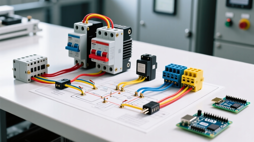

Understanding the 3-Phase DOL Motor Starter Architecture
When industrial facilities require reliable, high-torque starting for heavy machinery, the Direct-On-Line (DOL) motor starter remains the undisputed industry workhorse. A complete wiring diagram for motor starter configurations must account for two distinct but interconnected systems: the high-current power circuit and the low-current control circuit. In 2026, while solid-state and variable frequency drives (VFDs) handle complex motion profiles, the electromechanical DOL starter is still the most cost-effective and robust solution for constant-speed applications like industrial compressors, conveyor belts, and irrigation pumps.
This walkthrough focuses on a standard 10 HP, 460V AC, 3-phase induction motor with a Full Load Amp (FLA) rating of 14A. We will use a 3-wire control scheme (Start/Stop pushbuttons) with a 120VAC isolated control circuit, which is the safest and most common architecture in modern North American manufacturing plants.
Component Selection: NEMA vs. IEC Standards in 2026
Before pulling wire, you must select the correct contactor and overload relay. The market is split between NEMA (National Electrical Manufacturers Association) and IEC (International Electrotechnical Commission) standards. NEMA components are heavily oversized for extreme durability, while IEC components are compact, application-specific, and significantly more affordable.
| Feature | NEMA Size 2 (e.g., Square D 8539SCG3) | IEC Size S0 (e.g., Siemens 3RT2026) |
|---|---|---|
| Physical Footprint | Large, heavy-duty steel enclosure | Compact, DIN-rail mountable |
| Electrical Life (AC-3) | ~1,000,000 operations | ~1,200,000 operations |
| 2026 Avg. Pricing | $380 - $450 | $135 - $175 |
| Best Application | Harsh environments, high vibration | Control panels, OEM machinery |
For this walkthrough, we will utilize the Siemens 3RT2026 IEC contactor paired with a 3RU2116 thermal overload relay (adjustable 11-16A), representing the modern standard for panel builders.
Phase 1: Power Circuit Terminations (Line to Load)
The power circuit carries the full motor current. According to NFPA 70 (NEC) Article 430, motor branch circuit conductors must be sized at 125% of the motor FLA. For a 14A motor, the minimum ampacity is 17.5A. We will use 10 AWG THHN copper wire to account for voltage drop over distance and to ensure mechanical rigidity at the terminals.
Step 1: Line Side Wiring
Route your three phase conductors (L1, L2, L3) from the main disconnect switch or circuit breaker to the top terminals of the contactor (labeled 1/L1, 3/L2, 5/L3). Strip exactly 15mm of insulation. If using stranded wire, crimp on insulated ferrule sleeves to prevent strand fraying, which can cause hot spots and arc faults.
Step 2: Load Side & Overload Integration
Connect the bottom terminals of the contactor (2/T1, 4/T2, 6/T3) directly to the top input terminals of the thermal overload relay. Finally, route the output of the overload relay (labeled T1, T2, T3) to the motor peckerhead (terminal box). Critical Torque Spec: Use a calibrated torque screwdriver to tighten the Siemens 3RT20 main terminals to exactly 2.5 Nm (22 in-lbs). Under-torquing is the leading cause of terminal melting in IEC starters.
Pro-Tip: Always use a phase-rotation meter on the load side before connecting the motor. Swapping any two phase legs (e.g., L1 and L2) will reverse the motor's direction, which can severely damage centrifugal pumps or scroll compressors upon startup.
Phase 2: 3-Wire Control Circuit & Interlocking
The control circuit dictates when the contactor engages. To protect operators, we step down the 460V power to a 120VAC control voltage using an isolated control transformer. The 3-wire control diagram utilizes a momentary Start button (Normally Open), a momentary Stop button (Normally Closed), and a holding auxiliary contact.
Step 1: The Stop and Start Loop
Begin at the control transformer secondary (X1, 120VAC). Wire X1 to the Normally Closed (NC) terminal of the red Stop pushbutton. From the NC output of the Stop button, wire to the Normally Open (NO) terminal of the green Start pushbutton.
Step 2: The Holding (Seal-In) Contact
To keep the motor running after the operator releases the Start button, we wire an auxiliary NO contact (labeled 13/14 on the Siemens contactor) in parallel with the Start button. When the coil energizes, this auxiliary contact closes, bypassing the Start button and maintaining the circuit.
Step 3: Coil Termination
The output of the Start button and the auxiliary contact join and route to the A1 terminal on the contactor coil. The A2 terminal wires back to the X2 (neutral/grounded) side of the control transformer. Use 14 AWG wire for all 120VAC control wiring, color-coded blue or red per your facility's specific panel standards.
Phase 3: Overload Relay Integration and Calibration
The thermal overload relay protects the motor from drawing excessive current due to mechanical binding or phase loss. It contains a physical bimetallic strip that bends when heated, triggering a micro-switch.
Wiring the 95/96 NC Contacts
Locate the 95 and 96 terminals on the overload relay. These are Normally Closed (NC) dry contacts. You must wire these in series with the contactor coil. The most logical place is between the X2 transformer leg and the A2 coil terminal. If the motor overloads, the 95/96 contacts snap open, instantly dropping power to the A1/A2 coil and dropping out the main power contacts.
Dialing in the FLA
Using a flathead screwdriver, adjust the overload dial to the exact FLA listed on the motor nameplate (14A in our scenario). Do not set it to the maximum rating of the relay block; doing so will render the thermal protection useless and risk burning out the motor windings.
Diagnostic Matrix: Common Failure Modes & Edge Cases
Even with a perfect wiring diagram for motor starter layouts, field conditions introduce variables. Below is a diagnostic matrix for troubleshooting the most frequent 2026 field failures.
| Symptom | Root Cause | Multimeter Diagnostic Action |
|---|---|---|
| Contactor 'Chatters' loudly | Voltage drop across control circuit; coil receives < 85% nominal voltage. | Measure AC voltage directly across A1 and A2 while pressing Start. If below 102V, check for undersized control wire or failing transformer. |
| Motor hums but won't turn | Single-phasing (one power leg lost) or mechanical seizure. | Measure voltage between L1-L2, L2-L3, L1-L3 at the contactor line side. All should read ~460V. If one reads 0V, check upstream fuses. |
| Overload trips immediately | Incorrect FLA dial setting, or motor winding short. | Perform a megohmmeter (Megger) test on motor windings to ground. Check for < 1 Megohm resistance indicating insulation breakdown. |
| Coil burns out / melts | Sustained overvoltage (>110% nominal) or excessive ambient panel heat. | Log control voltage over 24 hours. Check panel ventilation and ensure enclosure doesn't exceed 40°C ambient. |
Code Compliance & Safety References
Wiring a motor starter is not just about making the machine run; it is about ensuring human safety and legal compliance. Before energizing any newly wired starter, you must adhere to strict Lockout/Tagout (LOTO) procedures as mandated by OSHA Standard 1910.147. Never assume a circuit is dead based on a pushbutton state; always verify zero energy with a CAT III or CAT IV rated multimeter.
Furthermore, ensure your motor controller complies with NEMA MG-1 standards for alternating-current motors and generators, specifically regarding the thermal protection coordination between the overload relay and the upstream branch-circuit short-circuit protection (fuses or inverse-time breakers). By following this step-by-step wiring diagram for motor starter circuits, you ensure a robust, code-compliant, and highly reliable installation that will withstand the rigors of modern industrial environments.