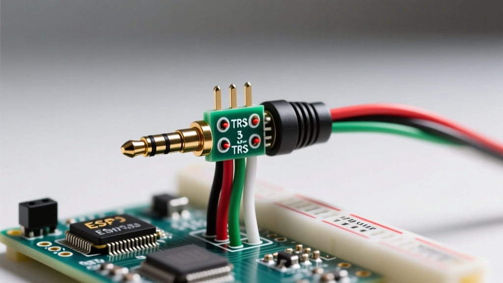

While USB-C and Bluetooth dominate consumer electronics in 2026, the 3.5 mm audio jack remains the undisputed standard for DIY audio projects, aviation headsets, ham radio interfaces, and custom in-ear monitors (IEMs). Whether you are repairing a high-end audiophile cable or building a custom TRRS breakout board, understanding the exact wiring diagram for 3.5 mm jack configurations is critical for signal integrity.
This comprehensive, step-by-step walkthrough will guide you through the physical anatomy, pinout standards, and precise soldering techniques required to terminate 3.5 mm connectors without damaging the delicate internal plastics or introducing signal noise.
TRS vs. TRRS: Decoding the Pinout Standards
Before applying heat to your soldering iron, you must identify whether your project requires a TRS (Tip-Ring-Sleeve) or TRRS (Tip-Ring-Ring-Sleeve) connector. The physical wiring diagram for 3.5 mm jack connections changes drastically between stereo audio and headset/microphone configurations.
| Connector Type | Segments | Primary Use Case | Standard Pinout Mapping |
|---|---|---|---|
| TRS | 3 (Tip, Ring, Sleeve) | Stereo Headphones, Line-Level Audio, Instrument Cables | Tip = Left Audio, Ring = Right Audio, Sleeve = Ground |
| TRRS (CTIA) | 4 (Tip, Ring 1, Ring 2, Sleeve) | Modern Headsets, Smartphones, PC Audio Combos | Tip = Left, Ring 1 = Right, Ring 2 = Ground, Sleeve = Mic |
| TRRS (OMTP) | 4 (Tip, Ring 1, Ring 2, Sleeve) | Legacy Devices (Pre-2012 Nokia/Sony Ericsson) | Tip = Left, Ring 1 = Right, Ring 2 = Mic, Sleeve = Ground |
Note: The CTIA (Cellular Telecommunications Industry Association) standard is the default for 99% of modern TRRS applications. Always wire to CTIA unless specifically interfacing with legacy hardware. For deeper historical context on these standards, refer to Wikipedia's comprehensive guide on Phone Connectors.
Essential Tools for Precision Audio Soldering
3.5 mm jacks, particularly panel-mount variants like the Switchcraft 35RAPC2BHN4 or PCB-mount CUI Devices SJ-3523-SMT, feature tightly packed solder lugs. Using the wrong tools will melt the internal insulating plastics, permanently shorting the connector.
- Soldering Station: Weller WE1010NA or Hakko FX-888D. Set temperature to 350°C (662°F) for standard 60/40 rosin-core solder.
- Solder Wire: Kester 44 Rosin-Core (0.031" / 0.8mm diameter). Do not use plumbing acid-core solder.
- Flux: Amtech NC-559-V2 or MG Chemicals 8341 No-Clean Flux Paste.
- Wire Strippers: Precision strippers capable of handling 24 AWG to 28 AWG stranded audio wire.
- Helping Hands: A third-hand tool with alligator clips to hold the barrel and cable steady.
Step-by-Step Walkthrough: Wiring a TRS 3.5 mm Jack
Step 1: Cable Preparation and Stripping
Strip the outer jacket of your audio cable back exactly 15mm (0.6 inches). Be extremely careful not to nick the inner enamel coating of the stranded copper wire. If you are using enameled magnet wire (common in DIY IEM cables), you must burn off or scrape the enamel coating using a fiberglass scratch pen or by briefly touching it with a 400°C soldering iron tip and a blob of fresh solder.
Step 2: Tinning the Conductors and Lugs
Never attempt to solder a raw wire directly to a jack lug. 1. Apply a microscopic amount of flux to the exposed copper strands. 2. Touch your tinned iron tip to the wire and feed in just enough solder to coat the strands (tinning). The result should be a shiny, silver-coated wire tip, no longer than 3mm. 3. Repeat the process for the solder lugs on the 3.5 mm jack. Pre-tin the Tip, Ring, and Sleeve lugs with a small dome of solder.
Step 3: Soldering the Connections
Slide the jack's plastic or metal housing barrel onto the cable before you begin soldering. Forgetting this step is the most common beginner mistake. 1. Hold the tinned wire against the pre-tinned lug. 2. Apply the iron tip to the junction for exactly 1.5 to 2 seconds. The solder should melt and flow into a smooth, concave fillet. 3. Remove the iron and hold the wire perfectly still for 3 seconds while the solder cools. Moving the wire during cooling creates a "cold joint," which looks dull and grainy and will eventually crack, causing intermittent audio dropouts.
Step 4: Strain Relief and Reassembly
For DIY cables, apply a small dab of hot glue or UV-curing resin over the soldered lugs and the cable jacket to act as a strain relief. This prevents the cable from pivoting and snapping the solder joints when plugged and unplugged. Slide the barrel up and thread it onto the jack body.
TRRS Wiring Walkthrough (CTIA Headset Standard)
Wiring a TRRS jack introduces a fourth conductor for the microphone. The physical spacing on a TRRS 3.5 mm jack is incredibly tight. According to CUI Devices' audio interconnect guidelines, bridging the Ring 2 and Sleeve lugs is the most frequent failure point in DIY TRRS cables.
- Tip (Left Audio): Solder the white or blue wire.
- Ring 1 (Right Audio): Solder the red wire.
- Ring 2 (Ground): Solder the bare copper or green ground wire.
- Sleeve (Microphone): Solder the yellow or black mic wire.
Pro-Tip for TRRS Soldering: Use a chisel tip (e.g., Hakko T18-D12) rather than a conical point. The flat edge transfers heat to the lug faster, reducing the dwell time and preventing the plastic core separating Ring 2 and the Sleeve from melting and causing an internal short.
Troubleshooting Common Wiring Failures
1. The Sleeve-to-Ring Short
Symptom: Audio plays, but sounds "hollow," missing vocals, or only plays out of one ear. When you partially pull the plug out, the audio returns to normal. Cause: A solder bridge between the Ring and Sleeve lugs, or melted internal plastic causing the lugs to touch. Fix: Use a desoldering wick (Goot Wick CP-2015) to remove excess solder. Inspect the gap between lugs under a magnifying lamp. If the internal plastic is melted, the jack is ruined and must be replaced.
2. Ground Loop Hum and Shielding Issues
Symptom: A persistent 60Hz hum or buzzing in the audio signal, especially when connecting a PC to an external amplifier. Cause: Incorrect shielding termination or a ground loop. As detailed in the seminal ePanorama Audio Wiring Guide, connecting the shield wire to both the Tip/Ring ground returns and the chassis ground can create an antenna for EMI (Electromagnetic Interference). Fix: Ensure the cable shield is tied only to the Sleeve (Ground) lug of the 3.5 mm jack. If building an unbalanced-to-balanced adapter, use a star-grounding topology to prevent ground currents from flowing through the audio signal return path.
3. Intermittent Crackling on Cable Movement
Symptom: Loud popping or crackling when the cable is bent near the jack. Cause: Lack of strain relief or a cold solder joint that has fractured microscopically. Fix: Re-flow the solder joints with fresh flux. Add heat-shrink tubing (3:1 shrink ratio with adhesive lining) over the cable entry point to lock the cable jacket to the jack's rear housing.
Final Verification with a Multimeter
Never plug a freshly wired DIY cable into an expensive amplifier or smartphone without testing it first. Set your digital multimeter to the continuity (beep) mode. 1. Plug a known-good 3.5 mm TRS plug into your newly wired jack. 2. Touch the multimeter probes to the exposed wire ends at the opposite end of the cable. 3. Verify that Tip maps to Left, Ring maps to Right, and Sleeve maps to Ground. 4. Ensure there is infinite resistance (OL) between the Tip and Ring, and Tip and Sleeve. Any continuity reading here indicates a short circuit that could damage your audio equipment's output stage.