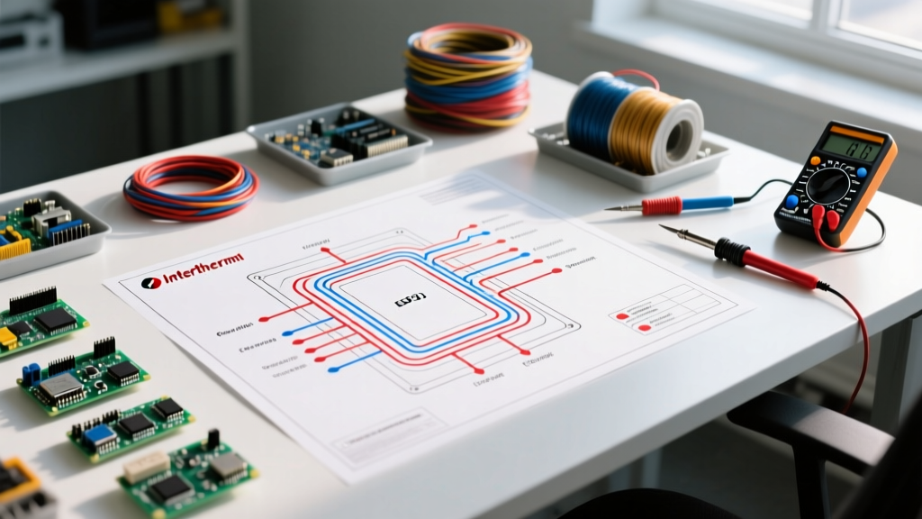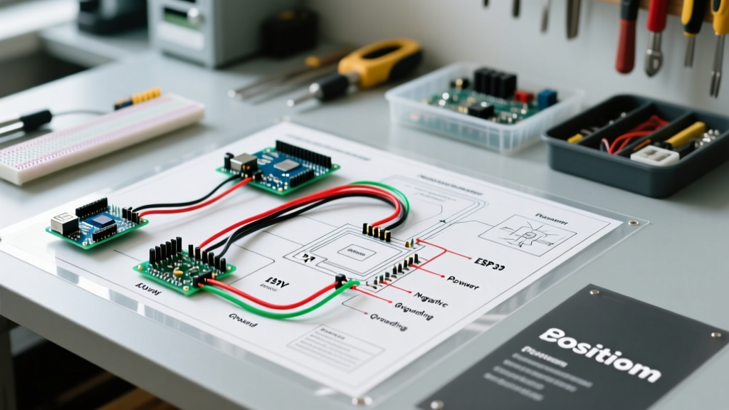

Understanding the Suburban RV Furnace Electrical Sequence
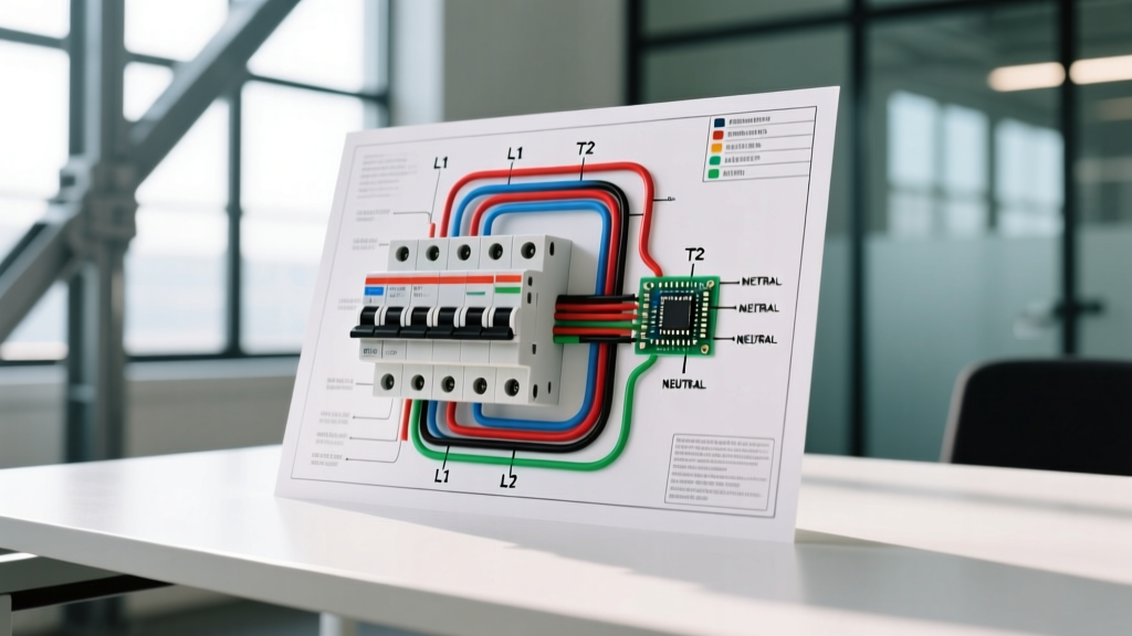
When the temperature drops at the campsite, a reliable forced-air heater is essential. However, electrical faults remain the leading cause of RV heating failures. Mastering the wiring diagram for Suburban RV furnace systems requires a clear understanding of the 12V DC sequence, safety interlocks, and high-current blower motor routing. Whether you are troubleshooting a Suburban NT-30S, an older DD series, or a modern Nautilus NQ20S, the foundational 12-volt control logic remains remarkably consistent.
This comprehensive walkthrough dissects the exact wiring pathways, terminal designations, and voltage requirements needed to safely install, diagnose, or repair your Suburban furnace. Before beginning any work, always disconnect the main 12V DC battery bank and shut off the LP gas supply at the tank.
Anatomy of the Suburban Control Circuit
Suburban furnaces, now manufactured and supported by Airxcel, rely on a centralized printed circuit board (PCB) to manage the ignition sequence. Unlike residential 24V AC systems, RV furnaces operate entirely on 12V DC power. The control board acts as the brain, monitoring safety switches and timing the spark ignition.
Core Electrical Components
- Control Board: The central relay and timing module (e.g., OEM part 520814 or Dinosaur Electronics UIB-64 replacement).
- Blower Motor: A high-draw 12V DC motor responsible for pushing air through the heat exchanger and proving airflow.
- Sail Switch: A pneumatic diaphragm switch that closes only when the blower achieves sufficient CFM output.
- High Limit Switch: A bi-metallic thermal switch mounted on the heat exchanger plenum that opens if exhaust temperatures exceed safe thresholds (usually 200°F to 250°F).
- Thermostat: A simple 2-wire mechanical or digital 12V DC switch that completes the control circuit.
- Gas Valve & Igniter: A 12V solenoid valve paired with a high-voltage spark electrode.
Wire Gauge and Routing Specifications
Voltage drop is the silent killer of RV furnace performance. The blower motor on a 30,000 to 40,000 BTU Suburban unit can draw between 7.5 and 11.5 amps during startup. If the wire gauge is too thin, or the run is too long, the voltage at the control board will drop below the 10.5V DC minimum threshold, causing the board to reset mid-cycle.
| Circuit Application | Recommended Wire Gauge | Insulation Color Code | Max Ampacity / Notes |
|---|---|---|---|
| Main 12V Power & Ground | 12 AWG (Stranded Copper) | Red (Power), White (Ground) | 20A inline fuse; required for runs over 10 feet |
| Thermostat Control Loop | 18 AWG (Stranded Copper) | Red/White or Blue/Yellow | Low current (<1A); 18 AWG is sufficient |
| Sail & Limit Switches | 16 AWG or 18 AWG | Orange, Yellow, or Brown | Carries control logic voltage only |
| Igniter High Voltage Lead | OEM Specific (Shielded) | Orange with thick silicone jacket | Do NOT substitute; carries 10kV+ spark pulse |
Expert Tip: Always use stranded, marine-grade tinned copper wire for RV applications. Solid copper wire will fracture under the constant vibration of highway travel, leading to intermittent open circuits that are incredibly difficult to diagnose.
Step-by-Step Wiring Walkthrough
Step 1: Main 12V DC Power and Ground
The main power feed originates from the RVs 12V DC distribution panel. Run a 12 AWG red wire from a dedicated 15A or 20A fused terminal on the distribution block directly to the +12V terminal on the Suburban control board. The ground path is equally critical. Run a 12 AWG white wire from the control board's GND terminal directly to the main chassis ground bus bar. Avoid daisy-chaining the furnace ground to nearby lighting circuits, as shared grounds introduce electrical noise that can interfere with the flame rectification sensor.
Step 2: Thermostat Control Loop
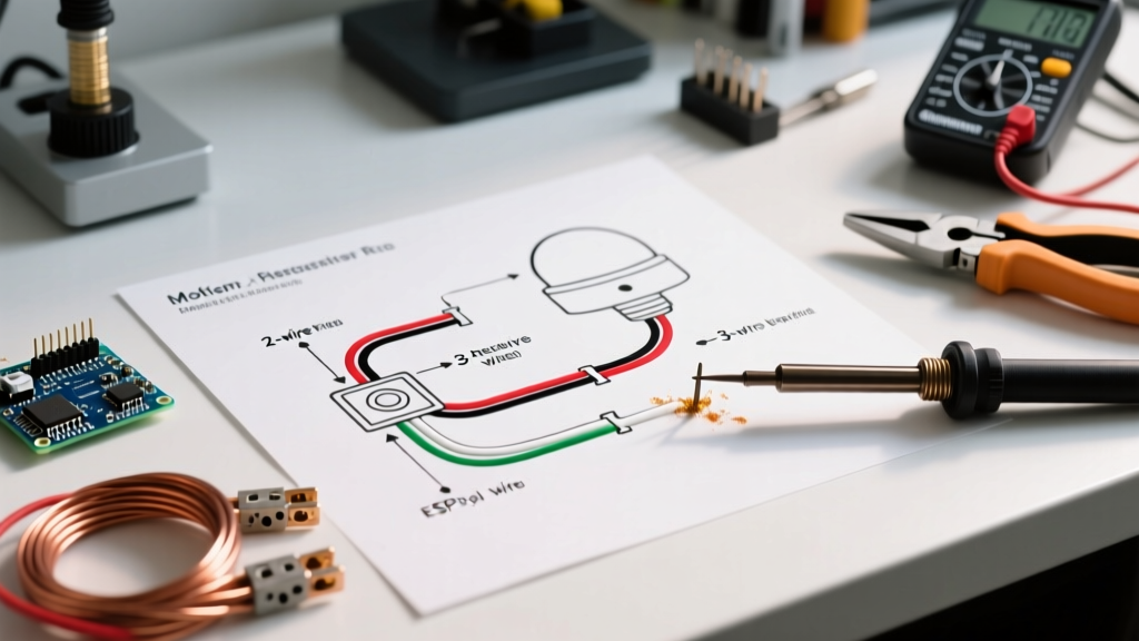
The Suburban thermostat operates as a simple dry-contact closure. Run an 18 AWG 2-conductor wire from the wall-mounted thermostat to the furnace. Connect one wire to the THRM (Thermostat) terminal on the control board, and the other to the +12V terminal (or a dedicated 12V source, depending on the specific thermostat model). When the ambient temperature drops below the set point, the thermostat closes the circuit, sending 12V to the THRM pin and waking up the control board.
Step 3: Airflow and Limit Safety Switches
Safety interlocks are wired in series to ensure the furnace cannot ignite without proper airflow. 1. The High Limit Switch is normally closed. Wire it from the 12V source to the LMT terminal on the board. 2. The Sail Switch is normally open. Wire it from the 12V source to the SAIL terminal. When the blower motor starts, it creates positive pressure in the vestibule, pushing the sail switch diaphragm inward. This closes the switch, sending 12V to the SAIL terminal, signaling the board that it is safe to open the gas valve.
Step 4: Gas Valve and Ignition Circuit
The gas valve solenoid is connected to the VALVE terminal and ground. The board pulses 12V to this terminal only after the sail switch closes. Simultaneously, the board sends a high-voltage pulse through the shielded orange wire to the IGN terminal, arcing across the electrode gap (set precisely to 1/8 inch or 3.2mm) to ignite the propane. Modern Suburban boards use flame rectification—reading the micro-amp current flowing through the flame to the grounded burner tray—to verify ignition. If no flame is detected within 3 to 4 seconds, the board cuts power to the VALVE terminal and initiates a 15-second blower purge cycle.
Diagnostic Voltage Readings and Failure Modes
When a Suburban furnace fails to ignite, technicians must follow the electrical sequence with a digital multimeter. According to safety and installation guidelines outlined in the NFPA 1192 Standard on Recreational Vehicles, all gas-burning appliances must have functional safety interlocks. Here is how to diagnose the most common wiring and component failures:
1. Blower Starts, But No Spark or Gas (Sail Switch Fault)
The Symptom: The fan runs indefinitely, but you hear no clicking and smell no gas.
The Diagnosis: The sail switch is failing to close. This is rarely an electrical wiring fault and usually a mechanical one. Lint, dog hair, or a rusted diaphragm prevents the switch from actuating.
The Fix: Probe the SAIL terminal with a multimeter. If you have 12V going into the switch but 0V at the board terminal while the blower is running, replace the sail switch (OEM part 232762, approx. $18).
2. Short Cycling (High Limit Switch Fault)
The Symptom: The furnace ignites, runs for 45 to 90 seconds, and then shuts down abruptly while the blower continues to run.
The Diagnosis: The high limit switch is opening prematurely due to restricted exhaust or a failing bi-metallic strip. Check the exterior exhaust vent for mud dauber nests or debris.
The Fix: Test for continuity across the limit switch terminals. If the switch is open at room temperature, it is defective and must be replaced.
3. Control Board Resets Mid-Cycle (Voltage Drop)
The Symptom: The furnace starts, the blower spins up, but right as the gas valve clicks open, the entire system powers down and restarts.
The Diagnosis: The gas valve solenoid draws an additional 1.5 to 2 amps. If your main power wiring is undersized (e.g., 14 AWG on a 25-foot run), this sudden current spike causes the voltage at the board to drop below 10.5V, triggering a brownout reset.
The Fix: Measure voltage directly at the +12V and GND terminals on the board while the blower is running. If it reads below 11.0V, upgrade the main power and ground wires to 10 AWG or 12 AWG.
2026 Component Replacement Cost Guide
When troubleshooting reveals a failed component rather than a simple wiring fault, sourcing OEM or high-quality aftermarket parts is critical. Below is the current pricing landscape for common Suburban furnace electrical components in 2026.
| Component | OEM Part Number Example | Average 2026 Cost | Replacement Difficulty |
|---|---|---|---|
| Control Board (Standard) | 520814 / 33081 | $95 - $135 | Easy (Plug and Play) |
| Dinosaur UIB-64 Universal Board | UIB-64 | $110 - $145 | Moderate (Requires splicing) |
| Sail Switch Assembly | 232762 | $15 - $22 | Easy (2 screws, 2 wires) |
| High Limit Switch | 230698 | $18 - $28 | Moderate (Requires plenum access) |
| 12V Blower Motor | 230982 (30k BTU) | $85 - $120 | Hard (Requires furnace removal) |
| Wall Thermostat (Digital) | 161154 | $35 - $55 | Easy (2-wire connection) |
Final Safety and Commissioning Checklist
After completing any wiring repairs or component replacements on your Suburban RV furnace, perform a full commissioning cycle. Reconnect the 12V DC power and open the LP gas valve. Run the stove burners for two minutes to purge any air from the gas lines. Set the thermostat to 80°F and listen for the sequence: blower startup, sail switch closure (audible click), rapid sparking, and flame ignition. Verify that the exhaust air outside is hot and free of soot, and use a combustible gas leak detector around the gas valve manifold to ensure no fittings were disturbed during the repair. Properly executed wiring not only ensures comfort but is the primary defense against carbon monoxide and fire hazards in your RV.