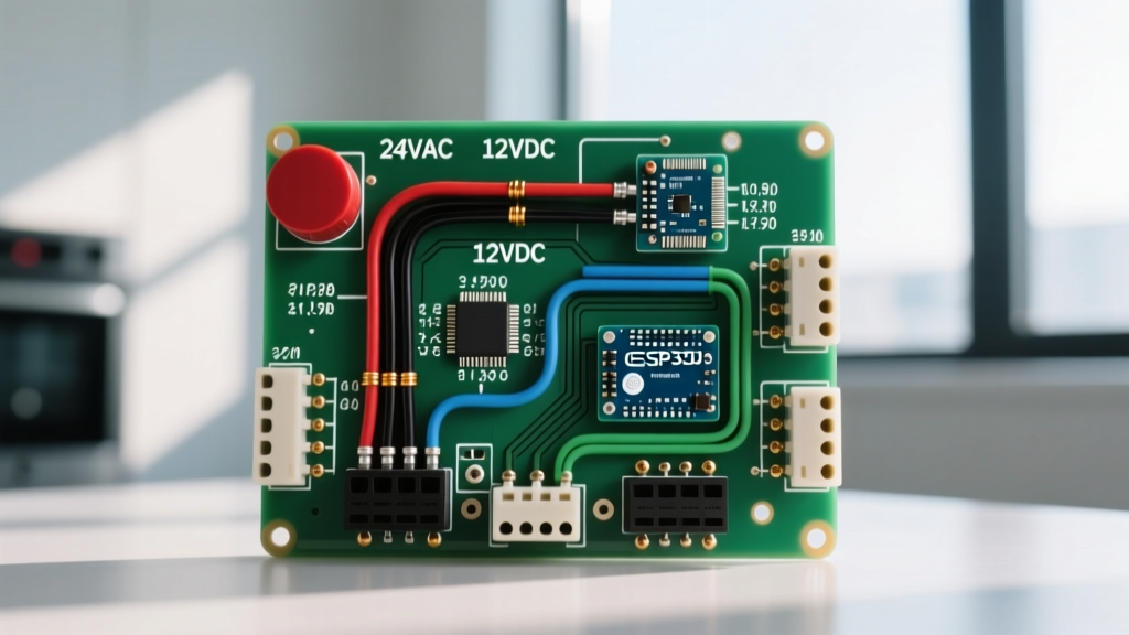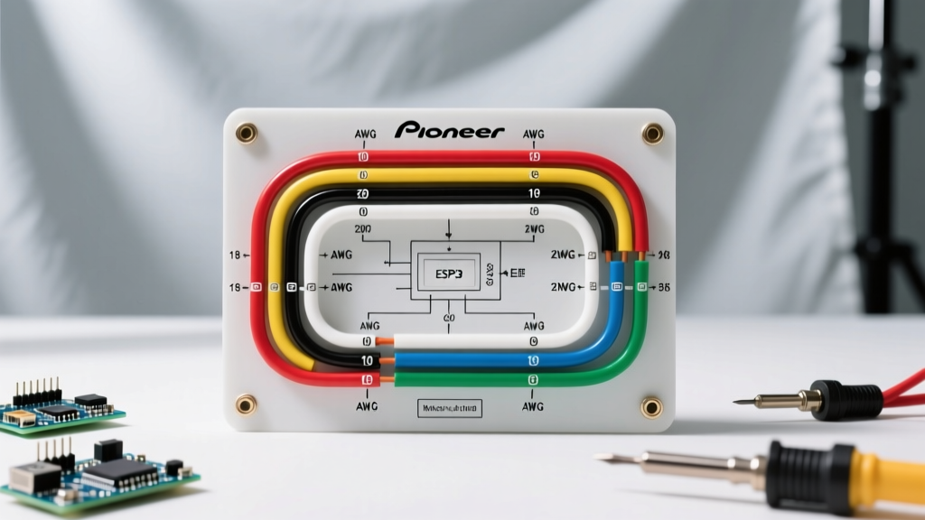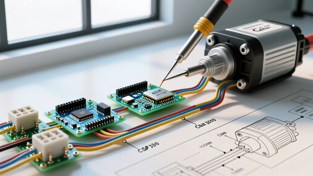

The Anatomy of a Club Car Starter-Generator
Wiring a starter-generator in a gas-powered golf cart requires a precise understanding of both the cranking circuit and the charging circuit. Unlike standard automotive alternators, the starter-generator in a Club Car DS or Precedent gas model serves a dual purpose: it acts as a high-torque series-wound motor to crank the engine, and transitions into a shunt-wound generator to recharge the 12V battery and power accessories once the engine is running.
Whether you are rebuilding a classic 1990s Club Car DS with a Hitachi S13-152 unit or wiring a newer Precedent equipped with a Mitsubishi T002T41071, the fundamental 5-terminal topology remains consistent. As of 2026, premium OEM replacement starter-generators range from $160 to $225, making correct wiring essential to avoid frying the internal armature or the external voltage regulator.
Expert Safety Directive: Before touching any terminal, disconnect the negative battery cable and disable the tow/run switch (if equipped). Always use insulated 10mm and 12mm deep sockets to prevent accidental shorting against the generator casing.
Hitachi vs. Mitsubishi Units: What You Need to Know
While the wiring diagram for a Club Car starter generator is largely universal across gas models, the physical terminal orientation varies. Hitachi units typically feature terminals arranged in a linear block on the rear brush plate, whereas Mitsubishi units often stagger the F (Field) and L (Light) spade connectors. Always verify your specific casing before cutting and crimping wires.
Terminal Identification & Wire Gauge Matrix
Selecting the correct wire gauge is critical. Undersized wiring on the main battery feed will cause severe voltage drop during cranking, leading to solenoid chatter and burnt contacts. According to the National Electrical Code (NFPA 70) guidelines for low-voltage DC automotive applications, overcurrent protection and wire sizing must match the maximum amperage draw, which can spike to 250A during initial cranking.
| Terminal ID | Function | Recommended Wire Gauge | Standard Wire Color | Connection Destination |
|---|---|---|---|---|
| B | Battery / Main Power | 10 AWG (or 8 AWG for long runs) | Red | Solenoid / Battery Positive |
| S | Start Signal | 12 AWG | Yellow or Red/White | Starter Solenoid (Small Post) |
| F | Field (Exciter) | 12 AWG | Green | Voltage Regulator (F Terminal) |
| L | Light / Charge Indicator | 14 AWG | Brown | Dashboard Charge Light |
| E | Earth / Ground | 10 AWG | Black | Engine Block / Chassis Ground |
Step-by-Step Wiring Walkthrough
Follow this exact sequence to ensure proper circuit isolation and prevent backfeeding, which is the leading cause of voltage regulator failure in DIY golf cart builds.
Step 1: Establishing the Ground (Terminal E)
Never rely solely on the mounting bolts for the ground path. The vibration of a single-cylinder gas engine will compromise the ground connection over time, leading to erratic charging.
- Crimp a 10 AWG ring terminal onto a black wire.
- Attach it directly to the E terminal on the generator.
- Route the other end to a clean, bare-metal spot on the engine block or the main chassis ground bus. Apply dielectric grease to prevent corrosion.
Step 2: Main Battery Feed (Terminal B)
The B terminal supplies raw battery voltage to the generator's armature and provides the heavy current required during the cranking phase.
- Run a 10 AWG red wire from the B terminal to the load side (output) of the starter solenoid.
- Pro Tip: For carts with high-draw accessories (lift kits, LED light bars), run this wire directly to a 150A ANL fuse block, then to the battery positive, bypassing the solenoid load side to ensure constant charging voltage.
- Torque the B-terminal nut to 12-15 in-lbs, as specified in Club Car's official maintenance documentation. Over-tightening will strip the soft brass terminal stud.
Step 3: The Field Circuit (Terminal F)
This is the most critical wire for the charging phase. The voltage regulator uses this wire to pulse the ground path to the generator's field coils, controlling the alternator's output.
- Connect a 12 AWG green wire from the F terminal on the generator to the F terminal on the voltage regulator.
- Ensure this wire is routed away from the spark plug wire to prevent electromagnetic interference (EMI), which can cause the regulator to misread the field resistance.
Step 4: Start Signal Routing (Terminal S)
The S terminal energizes the internal field coils specifically for the cranking sequence, turning the unit into a series-wound motor.
- Run a 12 AWG wire from the S terminal to the small "trigger" post on the starter solenoid.
- This wire is energized only when the ignition key is turned to "Start" and the microswitches under the accelerator pedal close.
Step 5: Charge Indicator (Terminal L)
The L terminal outputs a varying voltage that drops to near-zero when the generator is successfully charging.
- Connect a 14 AWG brown wire to the L terminal.
- Route this to the positive side of your dashboard charge indicator light. The negative side of the light grounds to the dash.
Voltage Regulator Pairing & Calibration
A starter-generator cannot function as an alternator without a voltage regulator. In 2026, most setups use a 4-terminal solid-state regulator (Terminals: B, F, L, E).
Wiring the Regulator:
- B (Battery): Connect to the same 12V source as the generator's B terminal (solenoid load side).
- F (Field): Connect directly to the generator's F terminal.
- L (Light): Connect to the generator's L terminal (they share the dash light circuit).
- E (Earth): Ground directly to the chassis. Do not share this ground wire with the generator's E wire; run a dedicated ground to prevent ground-loop voltage drops.
Advanced Troubleshooting & Edge Cases
Even with a perfect wiring diagram for a Club Car starter generator, real-world variables can introduce complex faults. Use a digital multimeter (DMM) to diagnose these specific failure modes.
The LED Backfeed Anomaly
If you have upgraded your dashboard to LED indicator lights, you may experience a bizarre failure mode: the cart continues to crank even after releasing the key, or the generator refuses to charge. LEDs have extremely low resistance and lack the thermal properties of incandescent bulbs. This can allow a micro-current to backfeed from the L terminal through the dash circuit and into the S terminal.
The Fix: Solder a 1N4007 blocking diode in-line on the L terminal wire, with the stripe facing away from the generator. This forces current to flow in only one direction, eliminating the backfeed.
Intermittent Cranking & Brush Wear
If the solenoid clicks but the generator fails to spin, the wiring is often blamed. However, before tearing apart the harness, measure the resistance across the B and E terminals (with the battery disconnected).
- Normal Reading: 0.5 to 1.2 ohms.
- High/Infinite Reading: Indicates worn carbon brushes or a burnt commutator. OEM brushes should be replaced when they wear down to 0.4 inches. A set of premium copper-graphite brushes costs around $18 to $25.
Voltage Regulator Frying Due to Bad Ground
If your voltage regulator keeps melting or failing within weeks of installation, check the E terminal ground on the regulator itself. If the regulator lacks a solid ground, it will attempt to ground through the F or L circuits, pushing 12V through low-gauge 14 AWG wires not rated for the amperage, resulting in melted insulation and a destroyed solid-state board.
Final Verification Checklist
Before reconnecting the negative battery terminal, perform these final physical checks:
- Verify all ring terminals are heat-shrunk and sealed with marine-grade adhesive to prevent moisture ingress.
- Ensure the drive belt is tensioned correctly (approx. 1/2 inch of deflection at the midpoint). A loose belt will cause the generator to slip during cranking, drawing excessive amperage and potentially melting the B terminal wire.
- Confirm the tow/run switch is in the "RUN" position to allow the ignition circuit to function during your first start.
By adhering strictly to this wiring diagram and respecting the specific current requirements of each terminal, your Club Car's starter-generator will deliver reliable cranking torque and consistent 13.8V to 14.2V charging output for years to come.