
Understanding Marine Electromechanical Appliance Wiring
When treating a vessel's outboard motor and its associated control harness as a heavy-duty marine appliance, the ignition switch acts as the primary logic gate. Whether you are rewiring a center console or troubleshooting a faulty start circuit on a pontoon, having an accurate wiring diagram for Mercury ignition switch configurations is non-negotiable. A single miswired terminal can result in a dead short, frying the voltage regulator, or worse, leaving you stranded on the water.
In this appliance wiring tutorial, we break down the exact terminal mappings, wire color codes, and diagnostic continuity matrices for Mercury outboard ignition switches. We will cover the ubiquitous 3-pole, 4-pole, and 5-pole configurations, ensuring your marine DC grid operates safely and efficiently.
The Universal Terminal Matrix
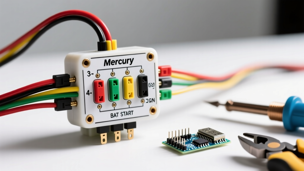
Before cutting any wire or crimping any terminal, you must understand the standardized letter designations stamped onto the back of Mercury ignition switch housings. These letters dictate the flow of 12V DC power and ground signals.
| Terminal | Designation | Function | Standard Wire Color |
|---|---|---|---|
| B | Battery | Receives constant 12V+ from the battery/solenoid. | Red (or Red/Purple) |
| I | Ignition | Sends 12V+ to the EFI computer, CDI, or gauges in 'Run'. | Purple |
| S | Start | Sends 12V+ to the starter solenoid only in 'Start'. | Yellow/Red |
| C | Choke | Activates the choke solenoid or prime bulb circuit. | Black/Yellow (Varies) |
| M | Magneto | Grounds the ignition coil to kill the engine in 'Off'. | Black/Yellow |
Wiring Diagram for Mercury Ignition Switch: By Pole Count
Mercury utilizes different switch architectures depending on the engine's horsepower, age, and whether it uses a tiller or remote throttle. Here is how to wire the three most common setups.
1. 3-Pole Configuration (Tiller & Small Displacement)
Commonly found on 2.5HP to 25HP tiller models (e.g., OEM part 87-88107A4), the 3-pole switch is the simplest marine appliance interface. It only features B, I, and M terminals.
- Run Position: Internal bridge connects B to I. The M terminal is isolated (open circuit).
- Off Position: Internal bridge connects M to ground (or the switch casing grounds the M terminal). B to I is open.
- Wiring Note: Because there is no 'S' terminal, the starter (if equipped) is usually engaged via a separate push-button switch wired directly to the solenoid, or the engine is pull-started.
2. 4-Pole Configuration (Standard Remote Throttle)
The 4-pole switch (e.g., OEM 87-88109A4 or Sierra 18-7638 replacement) is the industry standard for 40HP to 150HP remote-controlled outboards. It utilizes B, I, S, and M.
- Off: M is grounded to kill the engine.
- Run: B connects to I. M is isolated.
- Start: B connects to both I and S simultaneously. This powers the EFI/CDI while cranking the starter solenoid.
- Appliance Wiring Tip: Use a 14 AWG marine-grade tinned copper wire for the 'S' terminal. The starter solenoid draws minimal amperage (usually under 5A) to close the heavy-duty contacts, so 10 AWG is unnecessary here and makes crimping difficult.
3. 5-Pole Configuration (Choke & Prime Integration)
Older 2-stroke engines and specific carbureted models require a choke circuit to enrich the fuel mixture during cold starts. The 5-pole adds the C terminal.
- Choke/Prime Action: Pushing the key IN while in the 'Run' or 'Start' position bridges the B terminal to the C terminal, sending 12V to the choke solenoid or activating the fuel primer.
- Wiring Warning: Never wire the 'C' terminal to a constant 12V source. It must only receive power when the key is physically depressed. Continuous voltage will burn out the choke solenoid coil within minutes.
ABYC Compliance and Overcurrent Protection
When integrating the ignition switch into your boat's DC appliance panel, you must adhere to the American Boat & Yacht Council (ABYC) E-11 standards. According to NMEA and ABYC guidelines, the primary power feed (the 'B' terminal wire) must be protected by a fuse or circuit breaker.
Critical Safety Rule: The overcurrent protection device (fuse) for the ignition switch's Battery (B) wire must be installed within 7 inches of the battery's positive terminal. If the wire passes through a bulkhead before the fuse, it must be encased in a protective loom to prevent chafing and catastrophic short circuits.
For a standard 4-pole Mercury ignition switch, a 20-Amp inline blade fuse on the 10 AWG Red 'B' wire is standard practice. This protects the harness without nuisance-tripping during the voltage drop of engine cranking.
Multimeter Diagnostics: The Continuity Matrix
Before installing a new switch (or when troubleshooting an existing one), use a digital multimeter (like a Fluke 115) set to the Ohms/Continuity setting. Disconnect the battery first. Refer to this matrix to verify internal switch health:
| Key Position | B to I | B to S | M to Ground/Casing | B to C (Key Pushed In) |
|---|---|---|---|---|
| OFF | Open (OL) | Open (OL) | Closed (~0.0 Ω) | N/A |
| RUN | Closed (~0.0 Ω) | Open (OL) | Open (OL) | Closed (~0.0 Ω) |
| START | Closed (~0.0 Ω) | Closed (~0.0 Ω) | Open (OL) | Closed (~0.0 Ω) |
Note: If your 'M' terminal shows continuity to ground in the 'RUN' position, the switch is internally shorted and will kill the engine the moment you release the key from 'START'.
Common Failure Modes in Marine Environments
Marine appliances and outboard components face harsh, salt-laden environments. Here are the most frequent failure modes for Mercury ignition switches and how to resolve them:
- Galvanic Corrosion on the 'M' Terminal: Saltwater ingress causes copper oxidation on the Black/Yellow kill wire. This creates a high-resistance path, preventing the magneto from fully grounding, resulting in an engine that 'runs on' or diesels after turning the key off. Fix: Clean with contact cleaner and apply Marine Pro dielectric grease.
- Melted 'B' Terminal Housing: Caused by a loose spade connector creating high resistance and arcing. The heat melts the plastic phenolic housing. Fix: Never use standard vinyl crimps. Use adhesive-lined heat shrink terminals (e.g., 3M FP-301) and crimp with a proper ratcheting tool like the FTZ Industries FTZ-77.
- Sticking Start Solenoid: If the 'S' terminal remains engaged after releasing the key, the issue is rarely the ignition switch itself. It is almost always a welded contact inside the engine-mounted starter solenoid. Fix: Replace the starter solenoid (Mercury part 87-88119A1).
Frequently Asked Questions
Can I use an automotive ignition switch on my Mercury outboard?
No. Automotive switches typically use an 'ACC' (Accessory) terminal and lack the 'M' (Magneto) grounding terminal required to safely shut off a marine CDI or EFI system. Using an auto switch will result in an engine that cannot be turned off via the key. Always use marine-specific switches rated for Mercury Marine ignition architectures.
What is the difference between a magneto kill and an EFI kill circuit?
On older carbureted models, the 'M' terminal physically grounds the ignition coil's primary winding to stop spark generation. On modern EFI (Electronic Fuel Injection) engines, the 'M' terminal signals the ECU to cease firing the injectors and coils. The wiring diagram remains the same, but the amperage load on the 'M' circuit is significantly lower on EFI models.
Where can I find the exact wiring harness schematic for my specific serial number?
Mercury outboards are highly serialized. While the switch terminal logic remains universal, harness routing varies. Consult the BoatUS Expert Advice database or your local dealer's Mercury Parts Express portal using your engine's 1D or 2D serial number to pull the exact factory schematic.