
Decoding the Electric Scooter Wiring Diagram Owner's Manual
Most riders toss the documentation aside after unboxing, but when a commuter scooter suddenly loses power or throws an error code, the electric scooter wiring diagram owner's manual becomes your most valuable diagnostic asset. As of 2026, mid-tier and premium commuter scooters (like the Apollo City Pro or Segway Ninebot Max G2) utilize complex Brushless DC (BLDC) motor systems. These systems rely on precise phase commutation and Hall sensor feedback. Without the schematic provided in your manual, tracing a fault from the throttle down to the hub motor is virtually impossible.
This motor wiring tutorial will teach you how to read your manual's schematic, map it to physical wires, and use a multimeter to diagnose BLDC motor failures safely and accurately.
Mapping the Schematic: Phase Wires vs. Hall Sensors
When you open the wiring diagram in your owner's manual, the motor circuit will typically branch into two distinct harnesses connecting the controller to the hub motor. Understanding the distinction between these two circuits is the foundation of motor troubleshooting.
1. The Phase Wires (Power Delivery)
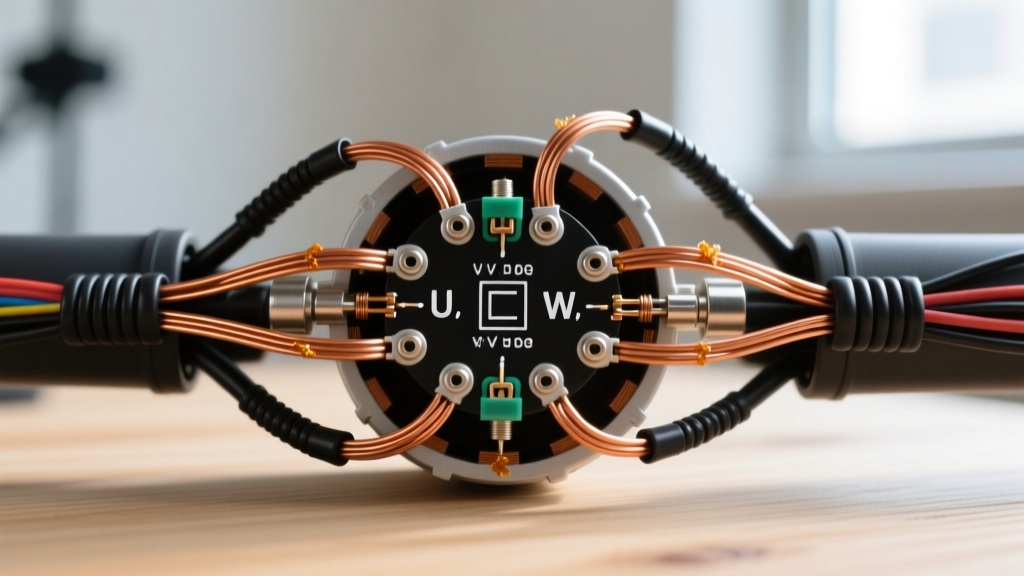
The manual will depict three thick lines running from the controller's MOSFET output stage to the motor stator. These are the Phase Wires (usually colored Yellow, Green, and Blue). They carry the high-amperage alternating current (AC) generated by the controller to spin the motor. In a standard 500W scooter motor, these wires can carry peak currents exceeding 25 amps during acceleration.
2. The Hall Sensor Wires (Position Feedback)
Alongside the phase wires, the diagram will show a cluster of five much thinner wires. These connect to the Hall Effect Sensors embedded inside the motor stator. The controller uses these sensors to determine the exact rotational position of the rotor magnets, allowing it to time the phase commutation perfectly. According to Texas Instruments' motor driver engineering resources, precise Hall sensor feedback is critical for preventing cogging, reducing noise, and ensuring smooth low-speed torque in BLDC applications.
Expert Safety Callout: Before probing any wires referenced in your manual, always disconnect the main battery pack and discharge the controller's main capacitors by bridging the positive and negative battery terminals with a high-wattage resistor (e.g., a 100-ohm 50W resistor). Failing to do so can destroy your multimeter or cause severe arcing.
Standard 8-Pin Motor Harness Color Mapping
While your specific owner's manual may use proprietary IEC symbols, the physical 8-pin JST or Higo waterproof connector on 90% of modern e-scooters follows a standardized color code. Use this table to cross-reference your physical wires with the manual's schematic.
| Wire Function | Standard Color | Wire Gauge (AWG) | Multimeter Test Mode | Expected Value |
|---|---|---|---|---|
| Phase A | Yellow (Thick) | 14 AWG | Resistance (Ohms) | 0.1Ω - 0.5Ω (Phase-to-Phase) |
| Phase B | Green (Thick) | 14 AWG | Resistance (Ohms) | 0.1Ω - 0.5Ω (Phase-to-Phase) |
| Phase C | Blue (Thick) | 14 AWG | Resistance (Ohms) | 0.1Ω - 0.5Ω (Phase-to-Phase) |
| Hall Power (+5V) | Red (Thin) | 22 AWG | DC Voltage | 4.8V - 5.2V |
| Hall Ground | Black (Thin) | 22 AWG | Continuity | Beep to Battery Negative |
| Hall Signal A | Yellow (Thin) | 22 AWG | DC Voltage (Spin Wheel) | 0V to 5V Square Wave |
| Hall Signal B | Green (Thin) | 22 AWG | DC Voltage (Spin Wheel) | 0V to 5V Square Wave |
| Hall Signal C | Blue (Thin) | 22 AWG | DC Voltage (Spin Wheel) | 0V to 5V Square Wave |
Step-by-Step Motor Wiring Tutorial Using the Diagram
When your scooter throws an error code (e.g., Error 15 or 18 on Xiaomi/Segway models, indicating a motor Hall or Phase fault), follow this sequence using your manual's diagram to isolate the failure.
- Locate the Controller Test Points: Use the owner's manual schematic to find where the motor harness plugs into the controller board. Disconnect the 8-pin motor connector.
- Test Phase Continuity: Set your multimeter to the lowest Ohms setting. Probe the three thick phase wires on the motor side of the connector (Yellow-Green, Green-Blue, Blue-Yellow). All three pairs should read nearly identical low resistance (typically under 0.5 ohms). If one pair reads 'OL' (Open Loop), you have a broken phase wire inside the motor axle—a common failure point requiring a $90-$150 motor replacement.
- Verify Hall Power Delivery: Reconnect the harness. Back-probe the thin Red and Black wires at the connector. Turn the scooter on. You must read exactly 5V DC. If you read 0V, the controller's 5V voltage regulator has failed, not the motor.
- Dynamic Hall Signal Testing: With the 5V power confirmed, back-probe the three thin signal wires (Yellow, Green, Blue). Lift the drive wheel off the ground and spin it slowly by hand. The multimeter should show the voltage toggling cleanly between 0V and 5V for each wire. If one wire stays stuck at 0V or 5V, that specific Hall sensor inside the stator is burnt out.
Common Failure Modes & Edge Cases in Scooter Motors
Wiring diagrams show the ideal state, but real-world conditions introduce edge cases that the manual rarely covers. Here are the most frequent physical failures that deviate from the schematic:
- Phase Wire Melt-Downs: High-amperage aftermarket controllers (like the VESC-based upgrades) can push 40+ amps through stock 14 AWG phase wires. This causes the insulation inside the hollow motor axle to melt, shorting the phases together. The wiring diagram won't show this thermal degradation, but a visual inspection of the axle exit point will reveal scorched silicone.
- Water Ingress in Higo Connectors: Despite IP65 ratings, capillary action can draw water into the motor connector during heavy rain. This causes the 5V Hall signal to short to ground, resulting in violent motor stuttering or controller lockouts. Always apply dielectric grease to the pins during reassembly.
- Sensorless Fallback Mode: Some advanced 2026 controller manuals detail a 'sensorless fallback' mode. If the 5-pin Hall harness is severed, the controller can attempt to commute the motor using Back-EMF (BEMF) zero-crossing detection. The scooter will 'cog' or jerk violently upon starting from a dead stop, but will smooth out once rolling. This is a limp-home feature, not a permanent fix.
Electrical faults in personal e-mobility devices can pose severe fire risks if high-current phase wires short out without proper overcurrent protection. Compliance with UL 2272 standards for personal e-mobility electrical systems dictates strict isolation and thermal cutoff requirements, which is why utilizing proper gauge wiring and respecting the manual's fuse ratings is non-negotiable. Furthermore, the U.S. Consumer Product Safety Commission (CPSC) strongly advises against bypassing factory thermal sensors or modifying motor harnesses outside of manufacturer specifications to prevent lithium-ion battery thermal runaway events triggered by controller shorts.
Frequently Asked Questions (FAQ)
What if my owner's manual shows a 6-pin motor connector instead of 8-pin?
A 6-pin diagram usually indicates a sensorless BLDC motor (3 phase wires + 3 BEMF sensing wires) or a combined UART/Hall harness where the throttle and display share a ground/power line with the motor sensors. Cross-reference the pinout legend on the specific page of your manual to confirm.
Can I swap the Yellow, Green, and Blue phase wires?
Yes, but it will change the motor's rotation direction. If you swap any two of the three thick phase wires, the motor will spin in reverse. If you are replacing a motor and the wheel spins backward, simply swap two of the thick phase wires at the controller connector—do not attempt to rewire the thin Hall sensors, as their sequence must match the physical magnet alignment.