
Mastering the Wiring Diagram for Oil Burner Systems
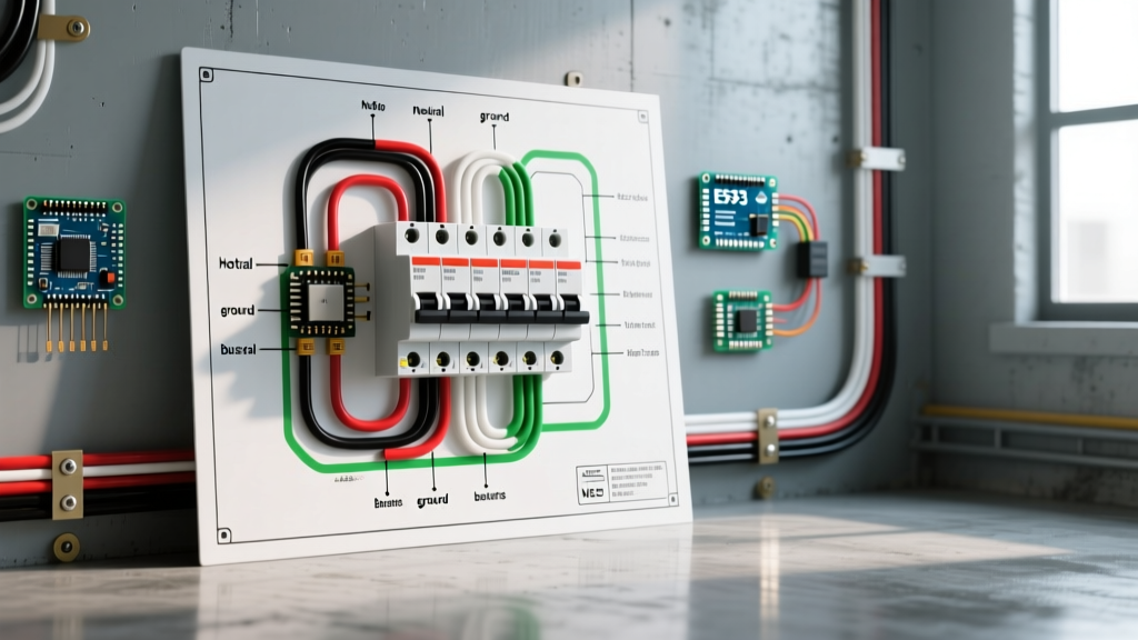
Wiring a residential oil-fired heating system requires strict adherence to both electrical codes and fuel safety standards. Whether you are retrofitting an older furnace or replacing a failed primary control on a boiler, understanding the exact wiring diagram for oil burner components is critical. In 2026, the industry standard remains dominated by interrupted-duty primary controls like the Beckett GeniSys 7505P and the Honeywell R7184B. These units manage the ignition transformer, fuel valve, and blower motor while monitoring the flame via a cad cell or flame rod.
⚠️ CRITICAL SAFETY WARNING: Oil burner primary controls handle 120V AC line voltage and control high-voltage ignition transformers (10,000V+). Always disconnect the main electrical service and shut off the oil supply valve before beginning any wiring. Verify zero voltage with a CAT III multimeter before touching terminals. Adhere strictly to NFPA 31 (Standard for the Installation of Oil-Burning Equipment) and local electrical codes.
Core Components and Terminal Definitions
Before pulling wire, you must understand the terminal layout on modern primary controls. While legacy systems used simple stack relays, modern microprocessor-based controls require precise termination.
- L1 & L2 (Line Voltage): 120V AC input. L1 is the hot leg (typically black), and L2 is the neutral leg (typically white).
- T-T (Thermostat/Limit Loop): A 120V AC series loop that connects the wall thermostat, aquastat (for boilers), or limit switches. When the T-T circuit is closed, the control initiates the pre-purge and ignition sequence.
- MOTOR (Blower/Fan): 120V AC output to the burner blower motor. The control internally switches this based on the timing sequence.
- IGN (Ignition Transformer): 120V AC output to the high-voltage ignition transformer. Active only during the trial-for-ignition period (usually 10-15 seconds).
- V1 / VALVE (Fuel Solenoid): 120V AC output to the oil pump solenoid valve (if equipped for clean starts/stops).
- F-F (Flame Sensor): Low-voltage input for the cad cell (cadmium sulfide photoresistor) or flame rod. These terminals are non-polarized.
Wire Gauge and Material Specifications
Using the correct wire gauge prevents voltage drop, which can cause microprocessor controls to fault out or ignition transformers to arc weakly. Below is the 2026 standard specification matrix for residential oil burner wiring.
| Circuit Type | Recommended Wire Gauge | Insulation Rating | Application Notes |
|---|---|---|---|
| Line Voltage (L1, L2, Motor, IGN) | 14 AWG Stranded Copper | THHN / 600V | Required for 120V circuits per NEC Article 430. Do not use 16 AWG for motor loads. |
| Thermostat Loop (T-T) | 18 AWG Solid Copper | Thermostat Wire / 300V | Standard 2-conductor or 3-conductor 18 AWG thermostat wire is acceptable for the 120V T-T loop. |
| Cad Cell Leads (F-F) | 18 AWG (Factory Pigtails) | High-Temp Silicone / Fiberglass | Never splice cad cell leads inside the burner tube. Use factory-sealed high-temp leads to prevent shorting. |
| Grounding (Earth) | 14 AWG Bare or Green | THHN / 600V | Must bond the burner chassis, motor casing, and primary control ground screw to the main panel ground. |
Step-by-Step Wiring Walkthrough
Follow this sequential workflow to wire a standard Beckett GeniSys or Honeywell R7184 primary control. This sequence ensures ground references are established before introducing line voltage.
Step 1: Establish the Equipment Ground
Flame rectification and cad cell circuits rely on a clean ground reference. Connect the main 14 AWG green ground wire from the junction box to the burner chassis ground lug. From the chassis, run a secondary 14 AWG jumper to the green ground screw on the primary control mounting base. A poor ground will cause erratic flame signal readings and nuisance lockouts.
Step 2: Wire the Line Voltage Input (L1 & L2)
Route your 14 AWG 120V AC supply into the control's knock-out hole using a proper Romex connector or flexible conduit fitting. Connect the black (hot) wire to the L1 terminal and the white (neutral) wire to the L2 terminal. Torque the terminal screws to 14 in-lbs to prevent arcing under vibration.
Step 3: Complete the Thermostat/Limit Loop (T-T)
The T-T terminals act as a switch. Wire the 18 AWG thermostat wire in series with the boiler aquastat or furnace limit switch, then to the wall thermostat. When the thermostat calls for heat, it closes the circuit, sending 120V from L1, through the limit switches, and back into the T-T terminal to wake up the control's microprocessor.
Step 4: Connect the Blower Motor and Ignition Transformer
Wire the black lead of the burner blower motor to the MOTOR terminal, and the motor's white lead directly to the L2 (neutral) bus in your junction box. Next, connect the primary side of the ignition transformer to the IGN terminal and the L2 neutral bus. Ensure the high-voltage secondary wires from the transformer are routed to the burner electrodes, maintaining a minimum 1-inch clearance from any grounded metal to prevent stray arcing.
Step 5: Terminate the Flame Sensor (F-F)
Route the cad cell leads through the designated low-voltage knock-out. Do not route F-F wires in the same conduit as 120V line wires; electromagnetic interference (EMI) can trick the microprocessor into seeing a false flame signal. Connect the two yellow cad cell wires to the F-F terminals. These are non-polarized, so orientation does not matter.
Step 6: Optional Solenoid Valve Wiring (V1)
If your oil pump is equipped with a clean-start/clean-stop solenoid valve, wire it to the V1 terminal and L2. This delays oil flow until the blower has established proper draft, and cuts oil instantly upon shutdown to prevent nozzle drip and after-fires.
Advanced Troubleshooting and Edge Cases
Even with a perfect wiring diagram for oil burner setups, field conditions introduce variables. Here are specific failure modes and how to diagnose them using a digital multimeter.
Edge Case 1: False Flame Detection (Lockout on Start)
Symptom: The control flashes a 'False Flame' error code before the ignition transformer even sparks.
Diagnosis: The cad cell is detecting infrared radiation from a hot refractory wall from a previous cycle, or the cad cell has failed internally (moisture ingress dropping its dark resistance below 20,000 ohms).
Fix: Disconnect the F-F leads. Set your multimeter to Ohms (Ω). Measure the resistance across the cad cell leads in the dark. It should read >20,000 Ω. If it reads lower, replace the cad cell eye (Part #5136 or equivalent, approx. $45). If the cell tests fine, reposition the sight tube to avoid direct line-of-sight to the glowing refractory.
Edge Case 2: Ignition Transformer Arcing but No Flame
Symptom: You hear the high-voltage spark, but the burner fails to ignite and locks out on safety.
Diagnosis: Voltage drop on the IGN circuit or improper electrode gap.
Fix: Measure AC voltage across the IGN and L2 terminals during the trial-for-ignition period. It must read ≥115V. If voltage is low, check for undersized wiring or a failing control relay. If voltage is correct, pull the burner assembly and verify the electrode gap is exactly 1/8 inch, with the porcelain insulators free of carbon tracking.
Edge Case 3: Motor Humming but Not Starting
Symptom: The blower motor hums, draws high amperage, and trips the internal overload.
Diagnosis: Missing neutral on the motor circuit or a seized pump.
Fix: Verify 120V AC between the MOTOR terminal and the motor's white neutral wire. If voltage is present, uncouple the motor from the fuel pump. If the motor spins freely uncoupled, the fuel pump is seized or the coupling is misaligned.
2026 Code Compliance and Best Practices
Modern electrical inspections are increasingly strict regarding heating equipment. According to the latest updates in the National Electrical Code (NEC / NFPA 70), all oil burner circuits must be protected by a dedicated 15A or 20A AFCI/GFCI breaker depending on local jurisdiction and the location of the appliance (e.g., unfinished basements or crawlspaces often mandate GFCI protection for 120V HVAC equipment).
Furthermore, always consult the manufacturer's specific technical documentation for your exact control model. Microprocessor firmware updates in 2025 and 2026 have altered the default pre-purge and post-purge timings on models like the GeniSys 7505P to improve combustion efficiency and reduce soot buildup. Never bypass the built-in safety lockout features, and always install a manual-reset emergency switch (Red Rover) at the top of the basement stairs or outside the utility room door as required by NFPA 31.
As of early 2026, expect to pay between $155 and $185 for a premium primary control, and roughly $120 for a professional-grade cad cell kit with high-temp silicone leads. Investing in OEM-specified components ensures the internal flame-sensing algorithms operate within their designed parameters, preventing costly nuisance service calls during the peak of winter.