
Beyond the Generic Electric Fence Wiring Diagram PDF
When agricultural operators and rural property owners search for an electric fence wiring diagram pdf, they are usually looking for a quick visual guide to connect their energizer to the fence line. However, blindly following a generic manufacturer schematic without considering local electrical codes and safety standards is a leading cause of equipment failure, livestock loss, and severe liability issues. In 2026, with the rising cost of high-tensile wire and advanced multi-zone energizers like the Gallagher M5800i (58 stored joules) or the Parmak Magnum Solar-Pak 12, protecting your investment through code-compliant installation is non-negotiable.
This guide dissects the standard electric fence wiring diagram through the strict lens of the National Electrical Code (NEC), UL 69 standards for fence controllers, and agricultural safety protocols. We will cover grounding electrode systems, wire gauge selection, lightning diversion, and the legal prohibitions that generic PDFs often fail to mention.
Anatomy of a Code-Compliant Wiring Schematic
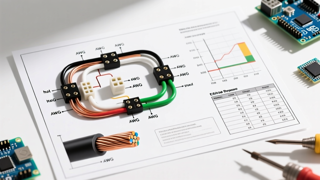
A proper wiring diagram for a high-output agricultural fence goes far beyond connecting a hot wire to a terminal. A compliant schematic must explicitly detail the separation of utility grounds from the fence ground, the integration of lightning arrestors, and the placement of in-line strainers.
Code Alert: According to UL 69 and standard agricultural safety guidelines, an electric fence controller must never be connected to a barbed wire line. The entanglement hazard turns a psychological deterrent into a lethal trap. Any wiring diagram PDF that shows a direct connection to barbed wire is fundamentally flawed and violates safety codes.
When interpreting your downloaded electric fence wiring diagram pdf, ensure it includes the following critical nodes:
- Energizer Isolation: A dedicated, weatherproof mounting post with non-conductive standoffs.
- Ground Return System: A multi-rod array explicitly separated from utility grounds.
- Surge Diversion: A gas-discharge tube or Transzorb-based lightning arrestor installed between the hot terminal and the ground system before the wire exits the building.
- Cutoff Switches: Heavy-duty, UV-stabilized porcelain or polycarbonate cutout switches for zone isolation.
Grounding Electrode Systems: NEC Article 250 Compliance
The most common point of failure—and code violation—in electric fence installations is the grounding system. The energizer pushes electrons out on the hot wire, but the circuit is only completed when the animal touches the wire and the current travels through the soil back to the ground rods. If your grounding array is undersized, the fence will not deliver the required minimum of 4,000 to 5,000 volts at the end of the line.
While the NEC (NFPA 70) primarily governs building electrical systems, NEC Article 250 provides the foundational rules for grounding electrodes that apply to the AC power supply feeding your fence energizer. Furthermore, agricultural safety standards mandate strict separation between your fence ground and your utility ground.
The 10-Foot Separation Rule
You must never tie your electric fence ground rods to your utility meter ground, building steel, or water pipe grounds. A fault on the utility line could energize your entire fence line with 120V/240V AC current, which is lethal to livestock and humans. Code requires the fence grounding electrode system to be installed at least 10 feet (3 meters) away from any other grounding electrode system.
Ground Rod Specifications & Soil Resistivity Matrix
For a standard 10 to 30-joule energizer, a single ground rod is entirely insufficient. Use the matrix below to determine your ground rod requirements based on soil conditions. All rods must be a minimum of 5/8-inch diameter, galvanized steel or copper-clad, and driven at least 6 feet into the soil.
| Soil Type | Moisture Level | Rod Count (Min) | Rod Spacing | Wire to Rods |
|---|---|---|---|---|
| Sandy / Arid | Low | 5 to 8 rods | 10 feet apart | Insulated 10 AWG Copper |
| Loam / Clay | Moderate | 3 rods | 10 feet apart | Insulated 12 AWG Copper |
| Peat / High Moisture | High | 2 rods | 10 feet apart | Insulated 12 AWG Copper |
Note: Always connect ground rods in parallel using heavy-duty galvanized clamps and a continuous run of insulated copper wire. Do not use aluminum wire for underground or ground-rod connections, as it will rapidly corrode due to galvanic reaction with the galvanized steel rods.
Wire Gauge, Tensile Strength, and Clearances
Generic diagrams often label the fence line simply as "fence wire." In reality, selecting the correct wire gauge and material is critical for voltage retention and physical durability. For permanent agricultural perimeters in 2026, 12.5 AWG High-Tensile Galvanized Steel (Class 3 coating) is the industry standard. It offers a breaking strength of approximately 1,500 lbs and resists sagging across long spans.
For temporary cross-fencing or wildlife exclusion, 14 AWG or 16 AWG stainless steel or tinned copper turbo-wire woven into poly-tape is preferred due to its lower resistance and portability.
Mandatory Clearances & OSHA Guidelines
When routing your fence wire near utility infrastructure, you must adhere to strict clearance codes. According to OSHA electrical safety guidelines and local utility easements, electric fences must never be installed directly under high-voltage transmission lines due to the risk of electromagnetic induction, which can induce lethal voltages onto the fence wire. Furthermore, fences must maintain a minimum horizontal clearance of 10 feet from utility poles and guy wires.
Lightning Protection: The Missing Link in Most PDFs
A massive omission in almost every free electric fence wiring diagram pdf found online is the integration of a dedicated lightning arrestor. A direct or near-miss lightning strike will send a multi-million-volt surge down the hot wire, straight into the energizer's output transformer, destroying the $400+ unit instantly.
Installation Protocol:
- Mount a gas-discharge tube lightning arrestor (e.g., D-Fence or PolyPhaser models) on the fence post nearest to the energizer.
- Connect one terminal of the arrestor to the hot fence wire using a short, direct jumper.
- Connect the other terminal to a dedicated, isolated ground rod driven at least 6 feet deep, located at least 10 feet away from both the energizer's ground system and any utility grounds.
- Ensure the path to the ground rod is straight; avoid sharp 90-degree bends in the grounding wire, which increase impedance and reduce the arrestor's ability to divert high-frequency surge currents.
Warning Signage and Legal Liability
Compliance is not just about how the wires are connected; it is also about public safety and liability. UL 69 and international standard IEC 60335-2-76 mandate the placement of warning signs along the fence line. If your fence runs adjacent to a public road, trail, or neighboring property, you must install highly visible, weather-resistant warning signs.
- Spacing: Signs must be placed every 300 feet (100 meters) and at every gate or public access point.
- Specifications: The sign must feature a yellow background with bold black lettering reading "WARNING: ELECTRIC FENCE".
- Material: Use UV-stabilized polycarbonate or corrugated PVC. Cheap vinyl signs will fade and become illegible within a single season of high UV exposure.
For comprehensive agricultural infrastructure planning and subsidy information regarding fencing for conservation purposes, property owners can consult resources provided by the United States Department of Agriculture (USDA), which frequently outlines safety and environmental compliance for perimeter fencing.
Troubleshooting Edge Cases and Code Violations
Even with a perfect wiring diagram, field conditions introduce variables that can lead to code violations or safety hazards. Watch for these common edge cases:
- Vegetation Loading: In high-growth areas, weeds touching the hot wire will cause severe voltage drop and can actually start fires in dry conditions due to arcing. Use a 2.0-joule minimum energizer for weed-heavy areas, and maintain a 3-foot vegetation clearance beneath the wire.
- Gate Handles: Never use uninsulated wire to create a gate loop. Use rated, UV-resistant gate handles with built-in tension springs. If a gate must carry current, use a heavy-duty insulated jump wire or a specialized underground gate cable (minimum 20,000V rating) buried at least 12 inches deep to prevent livestock from stepping on it.
- Multiple Energizers: It is strictly prohibited by code and physics to connect two separate energizers to the same fence wire. The pulse timing will eventually overlap, causing catastrophic feedback that will destroy both units. If you need to power separate zones, use a multi-zone energizer or physically isolate the fence lines with cutout switches.
Final Thoughts on Diagram Interpretation
An electric fence wiring diagram pdf is a valuable starting point, but it is not a substitute for a thorough understanding of electrical safety, soil physics, and local code requirements. By prioritizing NEC-compliant grounding separation, integrating proper lightning arrestors, and adhering to UL 69 signage mandates, you ensure your fencing system remains a safe, effective, and legally compliant asset for years to come.