
Introduction to Heat Pump Control Circuits
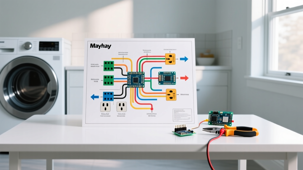
Wiring a heat pump thermostat is fundamentally different from configuring a standard gas furnace or straight air conditioning system. While a conventional AC unit only requires cooling signals, a heat pump must seamlessly transition between heating and cooling modes by reversing the flow of refrigerant. This requires a specialized wiring diagram for heat pump thermostat configurations that account for the reversing valve, auxiliary electric strip heat, and multi-stage compressor controls.
As of 2026, the widespread adoption of variable-speed compressors and A2L low-GWP refrigerants in residential HVAC systems means that precise low-voltage control signals are more critical than ever. A miswired terminal won't just cause discomfort; it can force the system to rely entirely on auxiliary resistance heating, potentially increasing your winter electric bill by 40% to 60%. This comprehensive appliance wiring tutorial will guide you through the exact terminal designations, wire gauges, and edge cases required for a flawless installation.
⚠️ CRITICAL SAFETY WARNING: Although the thermostat operates on a 24VAC low-voltage control circuit, the air handler and outdoor condenser contain lethal 240V high-voltage lines. Always turn off both the indoor air handler breaker and the outdoor disconnect switch before removing the old thermostat faceplate. Verify zero voltage at the air handler control board using a CAT III multimeter before proceeding.
Decoding the Heat Pump Terminal Designations
Before pulling new wire or connecting a smart thermostat, you must understand the standard terminal layout. Most modern heat pumps utilize an 18/8 or 18/10 AWG solid copper thermostat cable. Below is the industry-standard terminal mapping used by major manufacturers like Trane, Carrier, Lennox, and Rheem.
| Terminal | Standard Wire Color | Function & System Role |
|---|---|---|
| R / Rc / Rh | Red | 24VAC Hot (Power from transformer) |
| C | Blue or Black | 24VAC Common (Completes circuit for smart stats) |
| Y1 | Yellow | 1st Stage Compressor (Cooling & Heat Pump Heating) |
| Y2 | Light Blue | 2nd Stage Compressor (Variable speed staging) |
| W1 / AUX | White | 1st Stage Auxiliary Heat (Electric strip heat) |
| W2 / E | Brown or Pink | 2nd Stage / Emergency Heat (Bypasses heat pump) |
| O / B | Orange or Dark Blue | Reversing Valve Control (Crucial for heat pumps) |
| G | Green | Indoor Blower Fan Relay |
Step-by-Step Wiring Protocol for Heat Pump Systems
Step 1: Power Isolation and Existing Wire Audit
Remove the legacy thermostat faceplate. Before disconnecting a single wire, take a high-resolution photo of the existing terminal block. If your system uses a proprietary communicating thermostat (such as older Carrier Infinity or Lennox iComfort systems), standard 24VAC wiring diagrams will not apply; these use digital data buses (often labeled A, B, C, D) and require specific OEM replacements.
Step 2: Routing and Prepping 18/8 AWG Wire
If you are running a new line, use 18 AWG solid copper, 8-conductor (18/8) shielded cable. For runs exceeding 50 feet, voltage drop on the 24VAC circuit can cause contactor chatter or smart thermostat reboots. In these long-run scenarios, upgrade to 16/8 AWG. Strip exactly 1/4 inch of insulation using precision wire strippers (e.g., Klein Tools 11063W). If your cable is stranded rather than solid, you must crimp ferrule connectors onto the ends to prevent fraying and short circuits inside the terminal block.
Step 3: The Critical O/B Reversing Valve Configuration
This is the most common failure point in heat pump wiring. The O/B terminal controls the reversing valve, which dictates whether the system is in heating or cooling mode. However, manufacturers use opposite logic:
- Energized in Cooling (O Terminal): Used by Carrier, Bryant, Trane, Lennox, and Goodman. The valve defaults to heat; power is applied to switch to cooling.
- Energized in Heating (B Terminal): Used primarily by Rheem, Ruud, and Weatherking. The valve defaults to cool; power is applied to switch to heating.
Failure Mode: If you wire a Rheem system to the 'O' terminal logic, the system will blow cold air during winter. The thermostat will sense the temperature drop and immediately engage the W1 auxiliary strip heat, completely bypassing the efficient heat pump and massively inflating your energy costs.
2026 Smart Thermostat Compatibility Matrix
Upgrading to a smart thermostat requires a dedicated C-wire (Common) to power the Wi-Fi radio and display. Below is a comparison of the top-tier smart thermostats available in 2026 and how they handle heat pump-specific wiring.
| Feature | Nest Learning Thermostat (4th Gen) | Ecobee SmartThermostat Premium | Honeywell Home T10 Pro |
|---|---|---|---|
| Approx. Price (2026) | $279 | $249 | $189 |
| C-Wire Requirement | Optional (w/ internal battery) | Strictly Required | Strictly Required |
| O/B Auto-Detect | Yes (Software toggle) | Yes (Physical O/B terminal) | Manual Jumper/Menu |
| Aux Heat Lockout | Advanced (Weather predictive) | Yes (Compressor to temp) | Yes (Outdoor sensor req.) |
According to the U.S. EPA ENERGY STAR program, properly configured smart thermostats with auxiliary heat lockout capabilities can save homeowners up to 8% on annual heating costs by preventing the expensive electric strips from engaging when the outdoor temperature is above the system's balance point (typically 35°F to 40°F).
Advanced Troubleshooting: Edge Cases and Failure Modes
Even with a perfect wiring diagram for heat pump thermostat setups, field conditions can introduce anomalies. Here is how to diagnose the most complex edge cases:
- Auxiliary Heat Running Constantly (The Balance Point Failure):
- Symptom: The heat pump compressor (Y1) never engages in winter; only W1 runs.
- Diagnosis: Check the thermostat's 'Auxiliary Heat Lockout' setting. If the outdoor temperature sensor is faulty or disconnected, the thermostat defaults to assuming it is freezing outside and relies solely on strip heat.
- Fix: Verify the outdoor thermistor resistance (usually 10k ohms at 77°F) or enable the 'Compressor Minimum Temperature' setting in the smart thermostat app to 35°F.
- Reversing Valve Chatter or Humming:
- Symptom: A loud buzzing from the outdoor unit during mode transitions.
- Diagnosis: Voltage sag on the O/B wire. If the wire run is over 75 feet using 18 AWG, the 24VAC signal may drop below 18V at the solenoid, preventing it from fully seating.
- Fix: Replace the 18 AWG wire with 16 AWG, or install a hardstart kit / relay isolation module at the air handler.
- Smart Thermostat Wi-Fi Dropouts:
- Symptom: The Nest or Ecobee reboots randomly when the AC kicks on.
- Diagnosis: The thermostat is 'power stealing' from the Y1 or W1 wires because the C-wire is disconnected or broken.
- Fix: Run a dedicated C-wire from the air handler's 'C' terminal block. If running wire is impossible, install a 24VAC plug-in transformer (approx. $20) wired directly to the thermostat's Rc and C terminals, removing the jumper between Rc and Rh.
Code Compliance and Final Commissioning
When finalizing your installation, ensure compliance with local electrical codes and the U.S. Department of Energy's guidelines for heat pump systems. The thermostat cable must be secured to the framing within 12 inches of the wall penetrations and should never be run in the same conduit as 120V/240V line-voltage wiring to prevent electromagnetic interference (EMI) with modern communicating data buses.
Once wired, perform a manual commissioning sequence: Force the system into 'Cool' mode and verify the O/B valve engages and the outdoor fan spins. Next, switch to 'Heat' mode and confirm the reversing valve shifts (you will hear a distinct 'whoosh' of refrigerant). Finally, trigger 'Emergency Heat' to ensure the W2/E terminal activates the strip heaters while locking out the outdoor compressor. Proper commissioning guarantees that your wiring diagram translates into peak seasonal efficiency and longevity for your HVAC equipment.