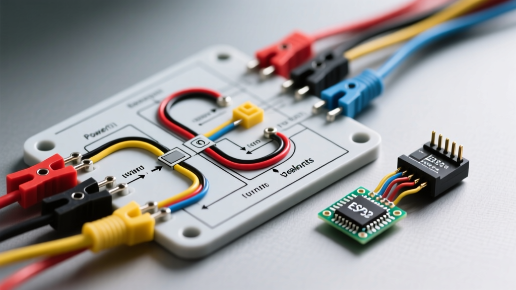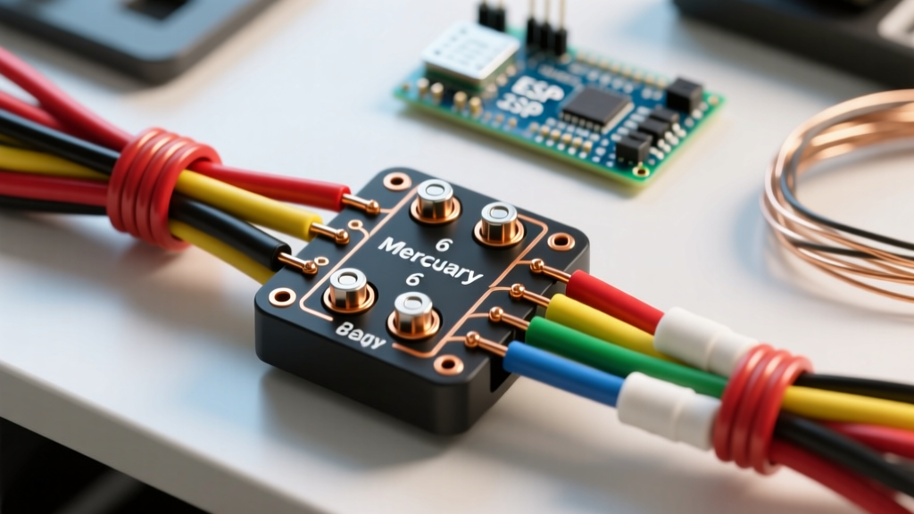

Introduction to Mercury Outboard Ignition Systems
While marine engines are not household appliances, treating your outboard's electrical harness with the same rigorous wiring discipline as high-end appliance repair is critical for reliability on the water. The ignition switch is the central command hub of your boat's dashboard. For decades, the standard wiring diagram for ignition switch on Mercury outboard motors has relied on a robust 6-pin configuration. Whether you are rigging a modern EFI FourStroke, an Optimax, or rebuilding a classic 2-stroke, understanding this 6-pin topology is essential for safe operation and accurate troubleshooting.
In 2026, despite the integration of digital CANbus networks on premium helm stations, the physical 6-pin analog switch remains the industry standard for primary engine cranking, kill circuits, and accessory wake-ups. This guide provides an expert-level breakdown of the pinouts, wire gauges, and diagnostic procedures required to wire or replace your Mercury ignition switch correctly.
Anatomy of the 6-Pin Mercury Ignition Harness
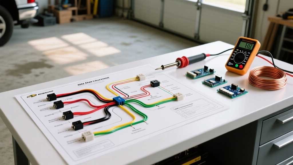
The standard Mercury outboard ignition switch utilizes a 6-terminal layout on the rear of the switch barrel. Unlike automotive switches that often use a monolithic plug, marine switches typically use individual spade terminals or a specialized 6-pin AMP (Automotive Marine Products) connector block. This design allows for modular harness repair but demands precise wire routing to prevent catastrophic short circuits.
Standard Mercury Wire Color Codes and Terminal Pinout
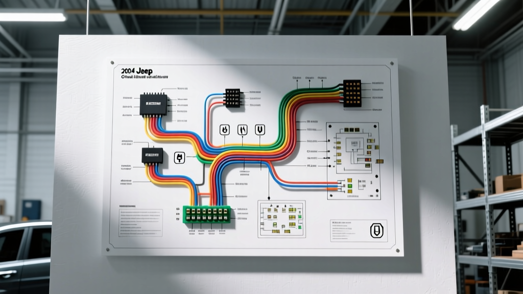
Adhering to the American Boat and Yacht Council (ABYC) E-11 standards and Mercury's proprietary color codes is non-negotiable. Miswiring the 'M' (Magneto) and 'S' (Start) terminals can instantly fry your engine's ECU or stator. Below is the definitive reference table for the 6-pin configuration.
| Terminal ID | Wire Color | Function | Recommended Gauge |
|---|---|---|---|
| B (Battery) | Red | 12V DC Main Power Feed (Fused) | 12 AWG |
| I (Ignition) | Purple | Accessories, Gauges, and ECM Wake-Up | 14 AWG |
| S (Start) | Yellow/Red | Starter Solenoid Trigger (Crank) | 12 AWG |
| C (Choke) | Blue or White/Blue | Choke Solenoid / Cold Start Enrichment | 14 AWG |
| M (Magneto) | Black/Yellow | Engine Kill (Grounds CDI/Stator to stop spark) | 14 AWG |
| G (Ground) | Black | Switch Illumination and Common Ground | 16 AWG |
Step-by-Step Wiring and Installation Protocol
When executing the wiring diagram for ignition switch on Mercury outboard setups, the physical installation is just as important as the electrical routing. Marine environments are highly corrosive; therefore, standard automotive crimps will fail within a single season.
- Disconnect the Battery: Always isolate the negative terminal on the main battery bank before touching the 'B' terminal to prevent arc welding your tools to the dashboard.
- Prepare the Wires: Strip exactly 1/4 inch of insulation. Do not nick the copper strands, as this creates a stress riser that will snap under boat vibration.
- Use Marine-Grade Heat Shrink Crimps: Utilize tinned-copper, adhesive-lined heat shrink ring terminals (brands like Ancor or 3M). The adhesive melts during heating, creating a waterproof seal that blocks capillary action from wicking saltwater up the wire jacket.
- Torque the Terminal Nuts: When securing wires to the switch studs, use a nut driver to apply approximately 15 to 20 in-lbs of torque. Over-tightening will strip the soft brass studs; under-tightening will cause high-resistance hot spots.
- Apply Dielectric Grease: Coat the exposed terminals and the rear of the switch barrel with a heavy coat of marine dielectric grease to displace moisture and prevent galvanic corrosion.
Multimeter Diagnostics: Testing the Switch Internals
If your engine is failing to crank or won't shut off, the switch is the prime suspect. You can map the internal continuity of the switch without removing it from the dash using a digital multimeter set to the Ohms/Continuity setting.
- OFF Position: Continuity between M and G. (This grounds the ignition system to kill the spark).
- RUN Position: Continuity between B and I. (Powers the gauges and ECU). M to G must be OPEN.
- START Position: Continuity between B, I, and S. (Powers accessories while engaging the starter solenoid).
- CHOKE Engagement (Push-In): Continuity between B and C. (Activates the choke solenoid on carbureted models or enriches the primer circuit).
Critical Safety Warning: If your engine continues to run after turning the key to the 'OFF' position, immediately shut it down via the emergency lanyard or by shifting into gear (if safe to do so). This indicates a broken Black/Yellow 'M' wire or a failed internal contact in the switch barrel. Running the engine without a functional kill circuit is a severe safety hazard.
Common Failure Modes and Edge Cases
Even with a perfect wiring diagram for ignition switch on Mercury outboard applications, environmental factors introduce unique failure modes. Here is what our master technicians look for when diagnosing stubborn electrical gremlins:
1. The 'Click-But-No-Crank' Voltage Drop
If you turn the key to 'START' and hear a single click from the solenoid but the engine doesn't turn over, the switch might not be the culprit. The Yellow/Red wire from the 'S' terminal travels a long distance to the starter solenoid. Corrosion at the inline bullet connectors can cause a severe voltage drop. Use your multimeter to measure DC voltage at the solenoid trigger wire while an assistant holds the key in 'START'. If you read anything less than 10.5V, you have harness resistance, not a bad switch.
2. AMP Connector Pin Corrosion
Many Mercury harnesses use a 6-pin rectangular plastic block. Salt air frequently breaches this block. If you suspect switch failure, use a specialized pin extraction tool to pop the terminals out of the plastic housing. Spray the contacts with CRC QD Electronic Cleaner, inspect for green copper oxide, and re-seat them. Never force a pin back into the block if the locking tang is bent.
3. Choke Circuit Overload
On older 2-stroke models, holding the key in the 'CHOKE' position for more than 5 to 7 seconds can overheat and melt the internal contacts of the 'C' terminal. Modern EFI engines use the 'C' terminal merely as a signal wire to the ECU for cold-start enrichment, drawing minimal current. Always verify whether your specific engine model uses a high-current choke solenoid or a low-current ECU signal before replacing the switch.
OEM vs. Aftermarket Marine Switches
When sourcing a replacement, you generally have two routes. The OEM Mercury switch (Part # 87-822708A1 or similar updated revisions) guarantees exact fitment and internal resistance specifications. However, premium aftermarket options from manufacturers like Cole Hersee (e.g., M-533 series) or Sierra Marine offer heavy-duty brass internals and superior waterproof sealing that often outlast the OEM units in harsh saltwater environments. Always ensure the aftermarket switch explicitly supports the 'Magneto Kill' (M terminal) configuration, as standard automotive switches lack this terminal entirely.
Compliance and Best Practices
According to the American Boat and Yacht Council (ABYC), the main power feed ('B' terminal) must be protected by an overcurrent device (fuse or breaker) located within 7 inches of the battery source. If your boat's wiring relies on a fuse located 15 feet away at the dashboard, you are violating marine safety standards and risking an electrical fire in the event of a chafed wire. For comprehensive rigging manuals and updated harness schematics, always consult the Mercury Marine Support Portal or reference the BoatUS Expert Advice archives for model-year-specific bulletins.
Final Thoughts on Harness Longevity
Wiring an outboard ignition switch is a straightforward process when you respect the color codes and prioritize marine-grade materials. By utilizing tinned wire, adhesive heat shrink, and rigorous continuity testing, you ensure that your vessel will start reliably on every pull of the key, leaving you free to focus on the water ahead rather than the dashboard behind.