
Understanding the Nest Thermostat E (GA01318-US) Control Circuit
Upgrading to a smart thermostat is one of the most effective ways to improve residential HVAC efficiency, but treating low-voltage control circuits as 'harmless' is a leading cause of equipment destruction and code violations. The wiring diagram for Nest Thermostat E (Model GA01318-US) operates on a 24 VAC Class 2 circuit. While this voltage will not cause lethal electrocution, improper wiring can instantly fry the $140 thermostat, destroy a $300 furnace control board, or create a fire hazard by violating National Electrical Code (NEC) separation requirements.
This guide approaches the Nest Thermostat E wiring diagram strictly through the lens of safety, NEC code compliance, and long-term HVAC system protection. According to the U.S. Department of Energy, proper installation and setup of smart thermostats are critical to realizing their energy-saving potential without compromising system safety.
Core Wiring Diagram & Terminal Mapping
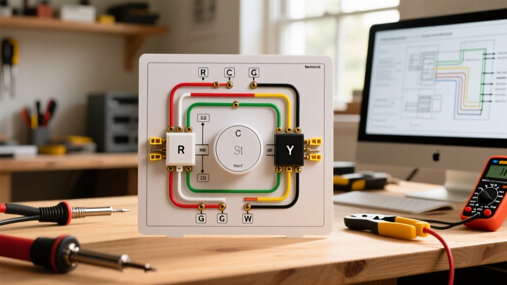
The Nest Thermostat E features a simplified terminal block compared to the flagship Nest Learning Thermostat. It is designed primarily for single-stage heating and cooling systems. Below is the definitive terminal mapping for standard 18 AWG solid copper thermostat wire.
| Terminal | Wire Color (Standard) | Function | Code & Safety Notes |
|---|---|---|---|
| R / Rc | Red | 24 VAC Power (Hot) | Must originate from the HVAC transformer. Never connect to 120V line voltage. |
| W | White | Heating Call (Stage 1) | Connects to the furnace control board heating relay. |
| Y | Yellow | Cooling Call (Stage 1) | Routes to the outdoor condenser contactor via the indoor board. |
| G | Green | Indoor Blower Fan | Energizes the fan relay independently of heating/cooling. |
| C | Blue / Black | Common (24 VAC Return) | Provides continuous power. Highly recommended to prevent power-stealing damage. |
| O/B | Orange / Dark Blue | Heat Pump Reversing Valve | O for cooling (Rheem/Ruud), B for heating (Carrier/Bryant). |
NEC Code Compliance: Article 725 & Low-Voltage Safety
Thermostat wiring falls under NEC Article 725, which governs Class 1, Class 2, and Class 3 Remote-Control, Signaling, and Power-Limited Circuits. The 24 VAC thermostat circuit is a Class 2 circuit. Compliance is not optional; it ensures that a fault in the low-voltage system cannot energize the home's ductwork or chassis with lethal line voltage.
Conduit Separation and Physical Barriers
A frequent code violation during DIY smart thermostat installations is running 18 AWG thermostat wire in the same conduit, junction box, or wall cavity as 120V or 240V line-voltage wiring without a physical barrier. NEC Article 725.136(A) strictly prohibits mixing Class 2 circuits with power, lighting, or Class 1 circuits unless they are separated by a continuous, firmly fixed barrier or the power conductors are in a metal raceway.
⚠️ SAFETY WARNING: If your existing thermostat wire shares a double-gang wall box with a 120V smart switch or outlet, you must install a UL-listed physical divider plate inside the box. Failure to do so risks a high-voltage short crossing into the 24V thermostat wire, which will instantly destroy the Nest Thermostat E and pose a severe shock hazard at the wall interface.
Wire Gauge and Insulation Standards
Always use minimum 18 AWG solid copper wire for runs under 100 feet. For runs exceeding 100 feet, upgrade to 16 AWG to prevent voltage drop below the 20 VAC threshold required by the Nest E's internal relays. Ensure the wire jacket is rated for in-wall use (CL2 or CL3 rating) to comply with fire safety codes regarding flame spread and smoke generation.
The C-Wire Requirement and Power Stealing Hazards
The Nest Thermostat E contains an internal lithium-ion battery. If a dedicated Common (C) wire is not present in your wiring diagram, the thermostat will attempt to 'power steal' or 'pulse' by slightly leaking current through the heating (W) or cooling (Y) circuits to charge its battery.
Why Power Stealing Violates HVAC Safety Margins
While Google designs the Nest E to support power stealing in a pinch, relying on it is a known cause of premature HVAC component failure. The micro-pulses can cause sensitive gas valve solenoids to chatter, inducer motor relays to degrade, or smart HVAC control boards to throw false diagnostic error codes. To maintain the safety and operational integrity of your HVAC system, a continuous 24 VAC return path via the C-wire is mandatory for code-compliant, best-practice installations.
When to Use the Nest Power Connector (GA02408-US)
If your home lacks an 18/5 wire setup and pulling new wire through finished walls is cost-prohibitive, use the Nest Power Connector (Model GA02408-US). Priced around $35, this device installs directly at the furnace control board or air handler, splicing into the R and C terminals and utilizing the existing G (Fan) and Y (Cooling) wires to multiplex power and data back to the thermostat. This is a UL-listed, code-compliant workaround that eliminates dangerous power-stealing behavior.
Step-by-Step Safety & Installation Protocol
Before touching a single wire, you must adhere to strict Lockout/Tagout (LOTO) procedures. The OSHA guidelines for controlling hazardous energy apply to residential HVAC servicing just as they do to commercial environments.
- Execute LOTO: Turn off the dedicated 15A or 20A circuit breaker for the indoor air handler/furnace AND the outdoor condenser unit. Place a physical lock or warning tag on the panel.
- Verify Zero Energy: Do not trust the thermostat display. Remove the old thermostat faceplate and use a Category III rated multimeter (e.g., Fluke 117) to test between the R wire and the C wire (or a known ground). The reading must be exactly 0.00 VAC.
- Inspect the Control Board Fuse: Locate the 3A automotive-style blade fuse on the furnace control board. If it is blown, the Nest E will not power on, and attempting to wire it without replacing the fuse will result in troubleshooting loops.
- Strip and Seat Wires: Strip exactly 1/4 inch (6mm) of insulation from the 18 AWG wires. Insert them into the Nest E's push-button terminals. Tug gently to ensure the brass contact has fully bitten into the copper. Exposed copper beyond the terminal block increases the risk of stray strand short-circuits.
- Restore and Test: Re-energize the breakers. The Nest E will boot, display a blinking blue light, and run a 5-minute system diagnostic to verify the wiring diagram matches the physical HVAC components.
Common Failure Modes & Troubleshooting Matrix
Even with a correct wiring diagram for Nest Thermostat E, miswiring at the furnace control board end or accidental shorts during installation will trigger specific failure modes. Use this matrix to diagnose issues safely.
| Symptom | Probable Cause | Corrective Action |
|---|---|---|
| Nest E screen is completely blank; no blinking lights. | Blown 3A fuse on HVAC control board due to R-to-C or R-to-G short during wiring. | Turn off power. Replace the 3A ATC blade fuse on the furnace board. Check for stray wire strands. |
| Display shows 'E73: No power to Rc wire'. | Breaker tripped, float switch open, or R wire not seated properly in the terminal. | Check main breakers. Inspect the condensate overflow float switch (often wired in series with the R or C wire). |
| AC blows warm air; Heat pump won't switch modes. | O/B terminal configuration mismatch in the Nest software menu. | Navigate to Settings > Equipment > Heat Pump. Toggle O/B orientation (O for most brands, B for Rheem/Ruud). |
| Furnace short-cycles; clicks rapidly but won't ignite. | Power stealing (no C-wire) is pulsing the gas valve relay. | Install a C-wire or the Nest Power Connector to provide continuous, clean 24 VAC power. |
Final Compliance and Inspection Notes
When finalizing your installation, ensure the thermostat backplate is mounted securely to the wall using the provided drywall anchors or directly into a stud. A loose backplate can cause the delicate 18 AWG wires to pull out of the spring-loaded terminals, leading to arcing or intermittent system failure. For comprehensive information on electrical safety standards and updates to the National Electrical Code, always refer to the National Fire Protection Association (NFPA). By treating the 24 VAC control circuit with the same respect as high-voltage wiring, you ensure your Nest Thermostat E operates safely, efficiently, and in full compliance with modern electrical codes.