
Understanding the Ramsey Winch Electrical Architecture
When outfitting a heavy-duty recovery vehicle or industrial flatbed, understanding the precise wiring diagram for Ramsey winch configurations is non-negotiable. Ramsey winches, such as the popular Patriot 9500 (REP 9500) and the RE8000 series, utilize high-torque, series-wound 12V DC motors. Unlike permanent magnet motors found in lighter ATV winches, series-wound motors draw massive amounts of current under load—often exceeding 400 amps at peak stall capacity. This extreme amperage dictates that your wire gauge selection, terminal crimping, and solenoid routing must be executed flawlessly to prevent catastrophic voltage drop, melted insulation, or electrical fires.
In 2026, the aftermarket recovery industry has largely standardized around high-strand-count welding cable and advanced solid-state or heavy-duty mechanical contactors (like the Albright DC88 or Trombetta 974 series). However, improper wiring remains the number one cause of premature winch failure. This guide provides a comprehensive breakdown of the wiring diagram for Ramsey winch solenoids, exact wire gauge matrices, and standard color code references to ensure your setup operates safely and efficiently.
Critical Wire Gauge Selection for High-Amp Draws
The most common mistake DIYers make when installing a 9,500 lb to 12,000 lb winch is undersizing the main power cables. Standard automotive primary wire (SAE J1128 Type GXL) lacks the flexibility and thermal mass required for the high-vibration, high-amperage environment of a winch motor. Instead, you must use SAE J1128 Type SGR welding cable or marine-grade tinned copper wire (such as those meeting ABYC E-11 standards). These cables feature hundreds of fine copper strands, offering superior flexibility and lower resistance.
According to Blue Sea Systems' wire sizing guidelines, voltage drop should be kept under 3% for critical high-amperage DC circuits. A 3% drop on a 12V system means you can only afford to lose 0.36V across the entire length of the positive and negative cables combined.
Winch Capacity to Wire Gauge Matrix
| Winch Capacity | Max Amp Draw (Stall) | Cable Length (One Way) | Recommended Gauge | Est. 2026 Cost / Ft |
|---|---|---|---|---|
| 8,000 lbs (e.g., RE8000) | 340 Amps | Under 10 ft | 2 AWG Welding Cable | $2.85 - $3.20 |
| 9,500 lbs (e.g., Patriot 9500) | 430 Amps | 10 ft to 15 ft | 1 AWG Welding Cable | $4.10 - $4.85 |
| 12,000 lbs (e.g., REP 12000) | 500+ Amps | Over 15 ft (Rear Mount) | 1/0 AWG (One-Aught) | $5.50 - $6.75 |
Expert Warning: Never measure cable length from the battery to the winch motor. You must measure the total circuit length: Battery Positive to Contactor, Contactor to Motor, Motor to Ground, and Ground back to Battery Negative. For a front-mounted winch on a full-size truck, total circuit length often exceeds 20 feet, necessitating an upgrade to 1 AWG or 1/0 AWG even for 8,000 lb winches.
Standard Color Code Reference for Ramsey Winches
While Ramsey provides specific wiring harnesses with their OEM solenoid packs, custom installations or replacement contactor packs require adherence to standard 12V DC color codes to prevent short circuits and ensure future serviceability.
- Main Battery Positive (+): Black (Standard OEM winch cable) or Red (Marine/Custom standard). Note: Many off-road winches use black for the main positive to hide dirt, but red is safer for custom builds.
- Main Chassis Ground (-): Black with a white stripe, or solid Black if Red is used for positive.
- Solenoid Control Wire (In/Power): Yellow or Orange (Switched 12V from the dashboard or remote pendant).
- Solenoid Control Wire (Out/Ground): Green or Blue (Switched ground to complete the low-amp solenoid circuit).
- Remote Pendant Wires: Typically a 3-pin or 4-pin flat connector. Pin 1: 12V Constant (Red), Pin 2: Spool In (Yellow), Pin 3: Spool Out (Green), Pin 4: Ground (Black).
The Core Wiring Diagram for Ramsey Winch Solenoids
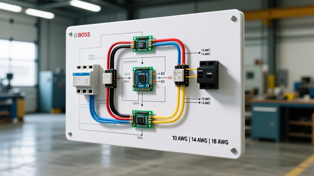
Modern Ramsey winches utilize a 4-terminal heavy-duty contactor (solenoid) rather than the older 3-terminal or 6-terminal relay packs. The 4-terminal design separates the high-amperage motor circuit from the low-amperage control circuit, drastically reducing the risk of the remote switch melting.
4-Terminal Contactor (Albright / Trombetta Style) Routing
- Terminal 1 (High Current Input): Connect the main positive cable from the vehicle's battery (or auxiliary winch battery) to this large 3/8" or 1/2" stud. Ensure an inline mega-fuse (400A to 500A) or ANL fuse is installed within 7 inches of the battery positive terminal.
- Terminal 2 (High Current Output): Connect the heavy-gauge cable running directly to the winch motor's positive terminal.
- Terminal 3 (Low Current Control - Power): Connect a smaller 12 AWG or 10 AWG wire to a switched 12V ignition source or the 'Power In' pin on your remote control switch. This energizes the internal magnetic coil.
- Terminal 4 (Low Current Control - Ground): Connect a 12 AWG or 10 AWG wire to a clean, bare-metal chassis ground or the 'Ground Out' pin on your remote switch.
For detailed schematic variations, referencing Mad Electrical's comprehensive guide to remote winch solenoids is highly recommended, as they provide exact visual maps for bridging terminals on older 6-post configurations if you are retrofitting a legacy Ramsey 50000 series.
Step-by-Step Installation & Routing Best Practices
Executing the wiring diagram for Ramsey winch systems requires more than just connecting wires; it demands rigorous mechanical and environmental preparation.
1. Terminal Crimping and Sealing
Do not use standard automotive crimpers for 2 AWG or 1 AWG cable. Use a heavy-duty hex-crimp tool or a hydraulic crimper to ensure a gas-tight connection. After crimping the copper lugs, slide a piece of 3:1 shrink tube with marine-grade adhesive lining over the joint and apply heat until the adhesive bleeds out. This prevents moisture ingress and copper oxidation, which are primary culprits of high-resistance connections.
2. Torque Specifications
Under-vibration, loose terminal nuts will arc and weld themselves to the stud. Use a calibrated torque wrench to secure your connections:
- 3/8" Terminal Studs: Torque to 12 - 15 ft-lbs.
- 1/2" Terminal Studs: Torque to 18 - 22 ft-lbs.
- Winch Motor Busbars: Torque to 8 - 10 ft-lbs (be careful not to strip the motor housing threads).
3. Environmental Protection
Apply a liberal coating of dielectric grease or Noalox (anti-oxidant compound) to all high-current terminal faces before mating them. This fills microscopic air gaps and prevents galvanic corrosion, especially if you are mating copper lugs to aluminum winch housings or zinc-plated solenoid studs.
Troubleshooting Common Wiring Failures
Even with a perfect wiring diagram for Ramsey winch setups, environmental factors and heavy use can lead to specific failure modes. Here is how to diagnose them:
Failure Mode 1: Solenoid Welding (Winch Runs Continuously)
Symptom: You release the remote switch, but the winch continues to spool in or out.
Cause: The high-amperage arcing inside the contactor has melted the copper contacts together, fusing them in the closed position.
Fix: Immediately disconnect the main battery cable. Replace the contactor pack. To prevent recurrence, ensure your winch motor brake is functioning correctly (a failing brake causes the motor to draw excessive current to hold the load) and never exceed the winch's rated line-pull capacity without a snatch block.
Failure Mode 2: Severe Voltage Drop and Motor Overheating
Symptom: The winch bogs down, the cables become hot to the touch, and the winch smells of burning ozone.
Cause: Undersized wire gauge, corroded terminal lugs, or a poor chassis ground.
Fix: Use a digital multimeter to measure the voltage directly at the battery, and then at the winch motor terminals while under load. If the voltage at the motor drops below 10.5V, you have excessive resistance in the circuit. Clean all grounds to bare metal, upgrade to 1/0 AWG cable, and verify all crimps are gas-tight.
Conclusion and Further Resources
Wiring a heavy-duty recovery system requires strict adherence to electrical principles. By following the correct wiring diagram for Ramsey winch solenoids, utilizing SAE-compliant welding cable, and respecting torque and sealing specifications, you ensure your equipment will perform reliably when you need it most. For official torque specs, exploded parts diagrams, and warranty information, always consult the Ramsey Winch official support portal and cross-reference your specific model's serial number.