
The Critical Role of the Wiring Diagram for a Generator Transfer Switch
In the modern electrical landscape of 2026, standby power is no longer a luxury; it is a critical infrastructure requirement. Whether you are integrating a 22kW Generac Guardian series or a 26kW Kohler unit, the transfer switch acts as the central nervous system of your backup power setup. Reading and executing a wiring diagram for a generator transfer switch correctly is the difference between a seamless power transition and a catastrophic backfeeding event that could endanger utility linemen or destroy your home's appliances.
This comprehensive walkthrough breaks down the exact schematic interpretation, physical wiring steps, and National Electrical Code (NEC) compliance requirements for installing a 200-Amp service-entrance-rated transfer switch, such as the widely used Generac RTSW200A3. We will cover conductor sizing, torque specifications, and the notoriously complex neutral-to-ground bonding rules.
Pre-Wiring Safety and 2026 NEC Compliance
Before unrolling any THHN copper conductors, strict safety protocols must be established. Backfeeding occurs when generator power bypasses the transfer switch and travels back through the utility lines, stepping up from 240V to thousands of volts via the utility transformer. To prevent this, adherence to OSHA Control of Hazardous Energy (Lockout/Tagout) standards is mandatory.
- Verify Zero Voltage: Use a CAT III or CAT IV rated multimeter (like the Fluke 117) to test the main service panel. Test Line-to-Line (expect 240V before shutoff), then Line-to-Ground on both phases.
- Working Space Clearance: NEC Article 110.26 requires a minimum of 36 inches of clear working space in front of the transfer switch and 30 inches of width. Do not mount the switch in a cramped utility closet without proper clearance.
- Permitting: In 2026, nearly all municipalities require an electrical permit and a post-installation inspection for standby systems under NEC Article 702 (Optional Standby Systems). Consult the NFPA National Electrical Code for local amendments.
Decoding the Schematic: Line, Load, and Generator
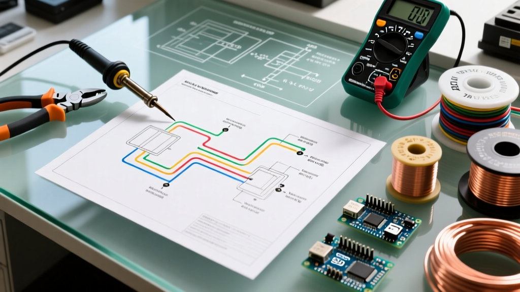
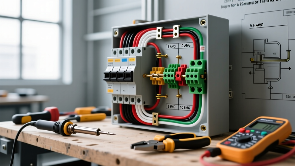
A standard wiring diagram for a generator transfer switch features three distinct termination zones. Understanding the flow of current through these zones is crucial for troubleshooting.
1. The Utility Infeed (Line Side)
This is where the meter base or main disconnect feeds the transfer switch. In a service-entrance-rated switch, this section contains the main utility breaker. The diagram will label these lugs as L1 (Phase A), L2 (Phase B), N (Neutral), and G (Ground).
2. The Subpanel Routing (Load Side)
The load side feeds your home's main distribution panel. The diagram will show these lugs mirroring the Line side. The critical difference here is that the neutral and ground bars in the downstream subpanel must remain isolated (separated), as the transfer switch now acts as the primary service disconnect where the neutral-to-ground bond occurs.
3. The Separately Derived System (SDS) Dilemma
This is where 90% of DIY wiring errors occur. According to NEC Article 250.20, if your generator has a bonded neutral (common in portable units and some air-cooled standbys), it is considered a Separately Derived System. If your transfer switch does not switch the neutral (a 2-pole switch), you will create a parallel neutral path, resulting in objectionable current on the grounding wire and tripped GFCI/AFCI breakers. Solution: Ensure your wiring diagram specifies a 3-pole (switched neutral) transfer switch if the generator neutral is bonded, or float the neutral at the generator alternator.
Step-by-Step Wiring Walkthrough
For this walkthrough, we are assuming a 200-Amp installation using a Generac RTSW200A3 and 2/0 AWG copper THHN conductors.
Phase 1: Utility Infeed (Line Side)
- Conduit Routing: Run 2-inch PVC or EMT conduit from the meter base to the top knockout of the transfer switch. Use a 90-degree sweep to prevent wire jamming.
- Pulling Conductors: Apply poly wire pulling lube (e.g., 3M Wire Pulling Compound) to four 2/0 AWG THHN wires (Black, Red, White, Green). Pull them through the conduit, leaving at least 8 inches of slack inside the enclosure.
- Termination: Strip exactly 3/4 inch of insulation using a Klein Tools wire stripper. Insert the Black wire into the L1 utility lug, Red into L2, White into the Neutral bar, and Green into the Ground bar.
- Torque Application: This is a critical 2026 NEC 110.14(D) requirement. Use a calibrated torque screwdriver to tighten the lugs to the manufacturer's exact specification (typically 250 in-lbs for 2/0 AWG). Under-torqued lugs cause thermal runaway and fires.
Phase 2: Subpanel Routing (Load Side)
- Route another 2-inch conduit from the bottom knockout of the transfer switch to the top of your existing main subpanel.
- Pull four new 2/0 AWG conductors. Connect them to the Load Side lugs on the transfer switch, matching the color coding (Black to L1, Red to L2).
- At the subpanel, connect the Black and Red wires to the new 200-Amp main breaker. Connect the White wire to the isolated Neutral bar and the Green wire to the Ground bar. Do not install a bonding screw or strap in this subpanel.
Phase 3: Generator Connection and Control Wiring
Standby generators require both high-voltage power conductors and low-voltage control wiring to signal the transfer switch to change states.
- Power Conductors: Route 2/0 AWG wires from the generator's main circuit breaker to the 'Generator' lugs on the transfer switch. Follow the exact L1/L2 phase rotation indicated on the schematic to ensure the utility and generator phases are synchronized.
- Control Wiring: Run the provided 14 AWG, 4-conductor control cable through 1/2-inch flexible liquid-tight conduit. Connect the wires to the terminal block labeled 'Gen Control'. These wires carry the 12V DC start signal and the utility sensing voltage.
Conductor Sizing and Torque Specification Matrix
Proper torque is non-negotiable. The following table outlines standard specifications for copper conductors at 75°C in a 200-Amp transfer switch environment. Always verify against the specific Generac Product Support manual for your exact model.
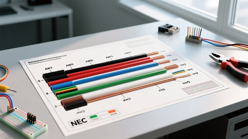
| Amperage Rating | Conductor Size (Copper) | Wire Type | Required Torque (in-lbs) | Stripping Length |
|---|---|---|---|---|
| 100A | #1 AWG | THHN/THWN-2 | 180 in-lbs | 5/8 inch |
| 150A | 1/0 AWG | THHN/THWN-2 | 225 in-lbs | 3/4 inch |
| 200A | 2/0 AWG | THHN/THWN-2 | 250 in-lbs | 3/4 inch |
| 400A (Parallel) | 300 kcmil | THHN/THWN-2 | 375 in-lbs | 1 inch |
Edge Cases: Thermal Runaway and Floating Neutrals
Expert Warning: A loose neutral connection on the load side of a transfer switch will not immediately trip a breaker. Instead, it causes a 'floating neutral' condition, where 120V circuits can experience voltage swings from 40V to 200V depending on the load imbalance, instantly destroying sensitive 2026 smart-home electronics and HVAC control boards.
To mitigate this, perform a thermal imaging scan using a tool like the FLIR C5 exactly 30 days after installation and under full load. Look for delta-T (temperature differences) greater than 15°F between the L1 and L2 lugs, which indicates unequal torque or oxidation.
Expert Troubleshooting FAQ
Why does the generator start, but the transfer switch won't engage?
Check the 12V DC control wiring. If the battery in the generator is weak (below 12.4V), it may have enough cranking amps to start the engine, but the voltage drop across the 14 AWG control wires will prevent the transfer switch solenoid from pulling the heavy mechanical contacts closed.
Can I use aluminum wire for the transfer switch connections?
Yes, but you must use AA-8000 series aluminum alloy conductors and apply an antioxidant compound (like Noalox) to the stripped wire before insertion. You must also upsize the wire by one gauge (e.g., use 4/0 AWG aluminum instead of 2/0 AWG copper for 200A) and adhere to the specific aluminum torque values listed on the switch label, which are typically 20% lower than copper values to prevent cold-flow deformation.
Does the transfer switch need its own grounding rod?
If the transfer switch is the first point of disconnect (Service Entrance Rated), the ground bar must be bonded to the neutral bar, and it must be tied to the building's primary grounding electrode system (ground rods or ufer ground). If it is a non-service-entrance switch mounted downstream of a main disconnect, do not bond neutral to ground, and do not add a secondary ground rod.