
The Anatomy of a 48V Electric Scooter Wiring Harness
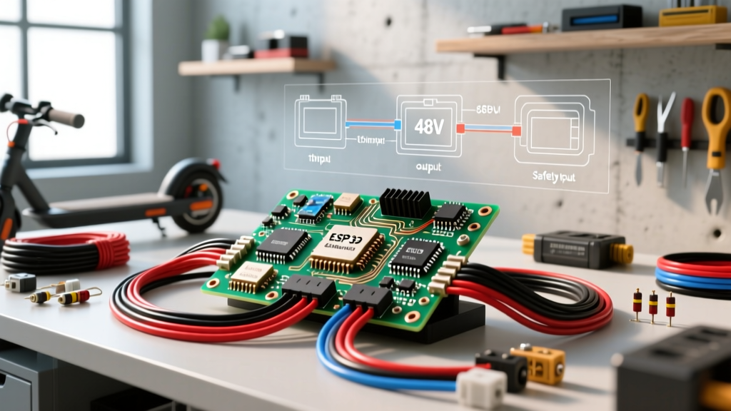
As micromobility technology matures in 2026, the 48V 1000W brushless DC (BLDC) platform has become the undisputed standard for high-performance commuter e-scooters. Whether you are repairing a blown controller on a generic dual-motor beast or building a custom rig from a bare frame, understanding the underlying electrical architecture is non-negotiable. A proper wiring diagram electric scooter layout is not just about making connections; it is about managing high inrush currents, isolating sensitive 5V logic from 48V power rails, and ensuring fail-safe braking.
This step-by-step walkthrough dissects the wiring harness of a standard 48V 22A square-wave controller (such as the KT-48SVPR or generic Vx1 clones). We will cover power integration, motor phase routing, hall sensor calibration, and peripheral logic wiring, complete with specific wire gauges, connector types, and multimeter diagnostics.
Essential Wire Gauge & Connector Matrix
Using undersized wire or incorrect connectors is the leading cause of thermal runaway in e-scooter battery enclosures. The table below outlines the strict requirements for a 48V 1000W (peak 22A continuous / 35A peak) system.
| Circuit Function | Recommended Wire Gauge (AWG) | Connector Type | Max Current Rating |
|---|---|---|---|
| Battery to Controller (Main Power) | 12 AWG (Silicone stranded) | XT90-S (Anti-spark) | 90A continuous |
| Motor Phase Wires (Yellow/Green/Blue) | 12 AWG (High-temp silicone) | 4.2mm Bullet / MR60 | 35A per phase |
| Hall Sensor & Throttle (Logic 5V) | 20 AWG to 22 AWG | JST-SM (5-pin / 3-pin) | 0.5A max |
| Headlight / Taillight (12V-48V step-down) | 18 AWG | JST-XH (2-pin) | 2A to 5A |
Phase 1: Battery Integration & The Precharge Circuit
The most critical moment in any e-scooter build is the initial connection between the 48V lithium-ion pack and the controller. Inside your controller, there is a bank of large electrolytic capacitors (typically four to six 1000µF 63V capacitors). When completely discharged, these capacitors act as a dead short for the first few milliseconds of connection.
The Inrush Current Problem
If you connect a fully charged 54.6V battery directly to an empty controller, the inrush current can easily exceed 150A. This results in a violent spark that will pit your XT90 connectors, weld the contacts, and potentially trip your Battery Management System (BMS) into a permanent protective lockout. According to data on lithium-ion safety profiles from Battery University, high-current shorts and micro-welding events severely degrade cell health and increase fire risks.
Wiring the Anti-Spark Solution
- Install an XT90-S Connector: Solder an XT90-S (anti-spark) to your controller's main power leads. This connector features a built-in 100Ω precharge resistor on one of the male pins.
- Connection Sequence: When plugging in, the resistor pin makes contact first, slowly charging the capacitors over 200-300 milliseconds. Once the voltage equalizes, the main pin engages, carrying the full current without a spark.
- Add a Master Kill Switch: Wire a heavy-duty 100A marine battery disconnect switch on the positive 12 AWG lead before the XT90 for physical theft deterrence and emergency shutoff.
Phase 2: BLDC Motor Phase & Hall Sensor Routing
Brushless hub motors require two distinct harnesses: the high-current phase wires and the low-voltage hall effect sensor wires.
Routing the Phase Wires
Connect the 12 AWG Yellow, Green, and Blue wires from the controller to the corresponding colors on the motor. Expert Tip: Coat the exposed bullet connectors in dielectric grease before mating them to prevent moisture ingress and galvanic corrosion, which causes high-resistance hot spots. Secure the phase wires with fiberglass braided sleeving to prevent them from rubbing against the scooter's swingarm.
Decoding the 5-Pin Hall Sensor Harness
The hall sensors tell the controller the exact rotor position. The standard JST-SM 5-pin connector follows this pinout:
- Pin 1 (Red): +5V Logic Power
- Pin 2 (Black): Ground (GND)
- Pin 3 (Yellow): Hall Sensor A Signal
- Pin 4 (Green): Hall Sensor B Signal
- Pin 5 (Blue): Hall Sensor C Signal
The 36-Combination Dilemma: If your controller and motor harnesses do not share the exact same color coding for the Yellow, Green, and Blue signal wires, the motor will stutter, draw massive current, and fail to spin. There are 36 possible combinations of phase and hall wiring. Never guess. If the colors do not match 1:1, use a multimeter to map the hall signals or use a programmable controller (like a VESC or Sabvoton) that features 'auto-detect' hall mapping.
Phase 3: Throttle, Brakes, and UART Display
The low-voltage logic harness controls how the scooter responds to rider input. Wiring these incorrectly can result in a runaway scooter, a severe hazard that the U.S. Consumer Product Safety Commission (CPSC) frequently flags in micromobility incident reports.
Throttle Wiring (3-Pin)
Standard hall-effect throttles use three wires: Red (5V), Black (GND), and White/Green (Signal). The signal wire outputs a variable voltage from roughly 0.8V (idle) to 4.2V (full throttle). Ensure the connector is keyed correctly; reversing 5V and GND will instantly fry the throttle's internal IC.
Electronic Brakes (E-Brakes)
Most 48V controllers use Normally Open (NO) brake levers. When the lever is pulled, the two-pin circuit closes, sending a 5V logic high to the controller's brake pin, which immediately cuts power to the motor phase wires and optionally engages regenerative braking. Wire the left and right brake cut-off switches in parallel so that pulling either lever disables the throttle.
UART Display Integration
Modern displays (like the QS-S4 or P85) communicate via UART (Universal Asynchronous Receiver-Transmitter). The harness typically includes a TX (Transmit) and RX (Receive) wire. Cross these wires: the TX from the display must connect to the RX on the controller, and vice versa. If the display powers on but shows a 'Communication Error 09', your TX/RX lines are likely swapped or suffering from a voltage drop due to undersized 22 AWG wires over a long handlebar run.
Critical Failure Modes & Multimeter Diagnostics
When your scooter fails to start, do not immediately replace the controller. Use a digital multimeter to trace the fault using this diagnostic matrix:
| Symptom | Probable Cause | Multimeter Test & Expected Value |
|---|---|---|
| Motor stutters and draws >30A without moving | Hall sensor misalignment or blown hall IC | Backprobe hall signal wires while spinning wheel by hand. Should toggle cleanly between 0V and 5V. |
| Throttle reads 0V at full twist | Broken signal wire or dead 5V regulator | Test Red/Black wires at throttle plug. Must read exactly 4.9V to 5.1V. If 0V, controller 5V LDO is fried. |
| Display powers on, but no wheel movement | Brake lever stuck engaged or MOSFET failure | Disconnect brake harness. If scooter works, replace brake lever. If not, test motor phases for continuity. |
| Massive spark and BMS shuts down on plug-in | Failed precharge resistor or shorted MOSFET | Set DMM to diode mode. Test Battery+ to Phase wires. A reading of 0.000 indicates a shorted MOSFET bank. |
Safety Standards & Final Assembly
Before sealing your scooter's deck or battery enclosure, perform a bench test. Elevate the drive wheel off the ground, apply 50% throttle, and monitor the motor temperature and controller heat sink. According to electrical safety guidelines outlined by the Occupational Safety and Health Administration (OSHA), all high-current DC connections must be mechanically secure and insulated to prevent arc flashes and short circuits.
Wrap all JST-SM and bullet connections in self-amalgamating silicone tape, which provides a waterproof, vibration-proof seal far superior to standard electrical tape. Finally, use hot glue or cable ties to secure the wiring harness away from the steering column and suspension linkages. A meticulously executed wiring diagram electric scooter layout not only guarantees peak performance but ensures your ride remains safe for thousands of miles of daily commuting.