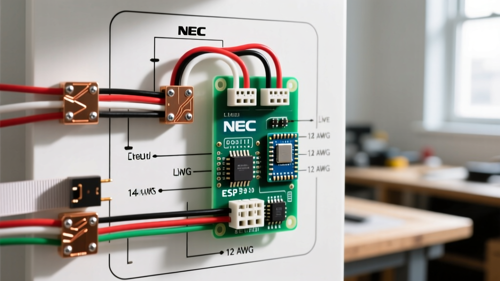

The Hidden Fire Hazard in Attic Ventilation
Every summer, improperly wired attic exhaust fans cause residential fires. The culprit is rarely the fan motor itself; rather, it is the undersized thermostat switching a massive inductive load. When you search for a wiring diagram for attic fan thermostat setups, most generic guides ignore the severe inrush currents (Locked Rotor Amperage) that arc and weld cheap bimetallic contacts together, leaving the fan running indefinitely until the motor overheats and ignites surrounding insulation.
As of the 2026 electrical season, with copper prices stabilizing around $0.85 per foot for 12/2 NM-B and local authorities having jurisdiction (AHJs) strictly enforcing the latest NEC motor circuit articles, compliance is non-negotiable. This guide provides a code-compliant wiring diagram for attic fan thermostat installations, prioritizing NEC Article 430 (Motors) and Article 422 (Appliances) to ensure your system is safe, legal, and fire-resistant.
Core NEC Code Requirements for Attic Fan Circuits
Before pulling any wire, you must understand how the National Electrical Code (NEC) classifies attic fans. They are not standard resistive loads like lighting; they are inductive motor loads. According to the NFPA 70 National Electrical Code, motor circuits require specific overcurrent protection and disconnecting means.
1. Dedicated Circuit vs. Shared Circuit
NEC Article 430 dictates that a single motor on an individual branch circuit must have conductors sized at 125% of the motor's Full Load Current (FLC). While a small 1/4 HP attic fan might only draw 3.5 amps, sharing this circuit with attic lighting or HVAC control boards is a severe violation if the combined load exceeds 80% of the breaker rating. A dedicated 20-amp circuit is the industry standard for residential attic fans up to 1/2 HP.
2. The Disconnecting Means (NEC 430.102)
You cannot rely solely on a breaker in the basement panel as a disconnect if the attic fan is out of sight. A local disconnect (such as a standard 20A toggle switch or a pull-out disconnect box) must be installed within sight of the fan motor, or the breaker must be lockable in the OFF position.
⚠️ SAFETY WARNING: Never bypass the thermal cutoff switch (firestat) built into the fan housing. If your fan lacks one, you must wire an inline high-limit thermostat (like the Broan 99.02.0053) in series to cut power if attic temperatures exceed 180°F, preventing motor meltdown.
Step-by-Step Wiring Diagram for Attic Fan Thermostat
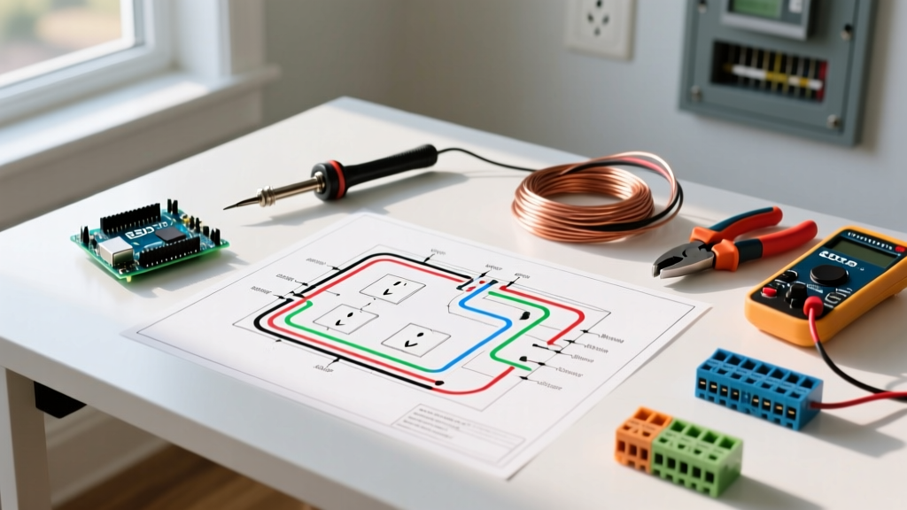
The safest configuration uses a Series Safety Loop. This ensures that both the ambient temperature thermostat and the high-limit firestat must be closed for the fan to receive power. Below is the exact wiring sequence from the panel to the motor.
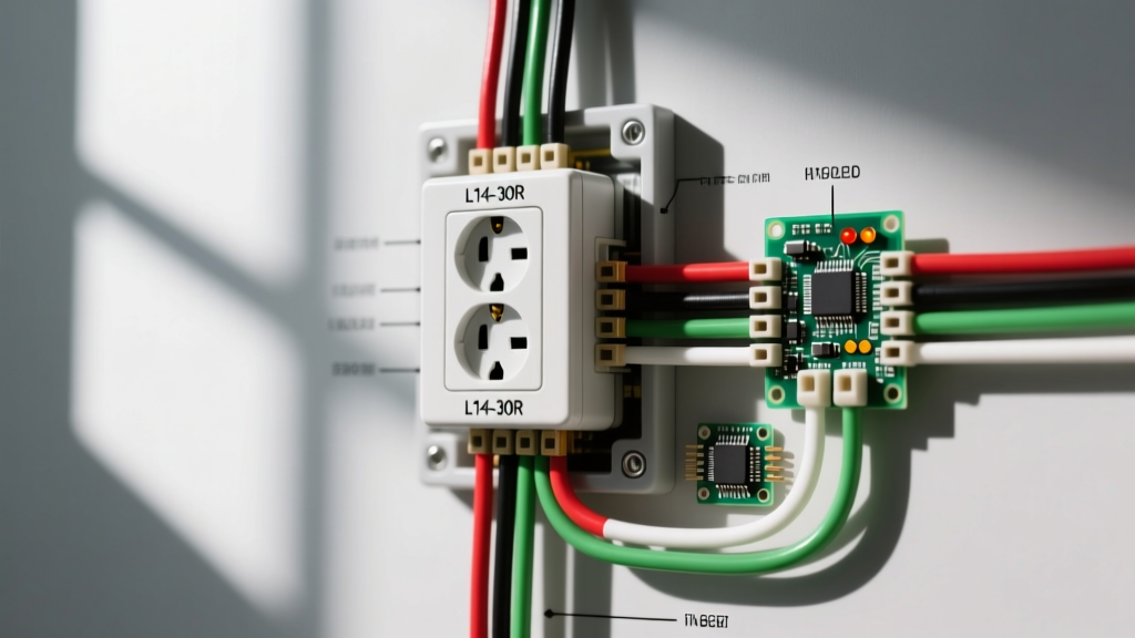
Phase 1: Panel to Junction Box
- Run 12/2 NM-B (Romex) from a dedicated 20A single-pole breaker in your main panel to a 4-inch deep metal junction box mounted near the fan.
- Connect the black (hot) wire to the breaker, the white (neutral) to the neutral bar, and the bare copper to the ground bar.
- At the junction box, bond the bare copper ground to the metal box using a green grounding screw and pigtail.
Phase 2: The Series Safety Loop (Line Side)
- Run a 12/2 cable from the junction box to the Firestat (High-Limit Switch). Connect the black wire to the Line terminal and the white wire (re-identified with black tape) to the Load terminal.
- Run another 12/2 cable from the Firestat's Load terminal to the Ambient Thermostat (e.g., Honeywell C7189U1005 or Broan 99.02.0054).
- Connect the incoming hot to the Thermostat's 'L1' (Line) terminal.
Phase 3: Thermostat to Fan Motor (Load Side)
- From the Thermostat's 'L2' (Load) terminal, run the switched hot directly to the fan motor's black lead.
- Splice all neutral (white) wires together using a purple or blue WingNut wire connector, bypassing the switches and thermostats, directly to the motor's white lead.
- Splice all ground wires together and bond to the motor chassis and all metal junction boxes.
Component Selection & Wire Sizing Matrix
Using the wrong wire gauge or breaker size for inductive loads is the leading cause of nuisance tripping and melted insulation. Use the matrix below to size your components based on the motor's nameplate data. Data aligns with 2026 copper ampacity standards and NEC Table 310.16.
| Motor HP | FLC (Amps) | LRA (Inrush) | Min Wire AWG | Max Breaker (Inverse Time) | Thermostat Rating Required |
|---|---|---|---|---|---|
| 1/6 HP | 2.2A | 12A | 14 AWG | 15A | 120V / 10A Inductive |
| 1/4 HP | 3.9A | 22A | 12 AWG | 20A | 120V / 15A Inductive |
| 1/3 HP | 5.2A | 34A | 12 AWG | 20A | 120V / 22A Inductive |
| 1/2 HP | 7.8A | 55A | 10 AWG | 25A | 120V / 30A or Contactor |
Note: NEC 430.52 permits inverse-time breakers to be sized up to 250% of the motor FLC to accommodate startup surges without tripping. Always default to the motor manufacturer's specified maximum overcurrent protection.
Critical Safety Failures & Edge Cases
Even with a perfect wiring diagram for attic fan thermostat setups, environmental and electrical edge cases can cause catastrophic failures. Watch out for these specific scenarios:
Contactor Welding Due to High LRA
If you are installing a powerful 1/2 HP or 3/4 HP gable fan (like the iLiving ILG8SF16V), the Locked Rotor Amperage (LRA) can exceed 40 amps. Standard line-voltage thermostats use a bimetallic strip that will physically arc and weld itself shut when breaking a 40A inductive load. The Fix: You must wire a 24V low-voltage thermostat to a 120V Definite Purpose Contactor (e.g., Packard C230B). The thermostat switches the low-amperage contactor coil, while the heavy-duty contactor contacts handle the motor's massive inrush current.
Thermal Creep in Poorly Ventilated Attics
If your attic lacks adequate soffit intake ventilation, the ambient temperature can easily exceed 140°F. Standard thermostats set to 110°F will run the fan continuously. According to the U.S. Department of Energy, continuous operation without proper intake air will pull conditioned air from your living space through ceiling penetrations, skyrocketing HVAC costs and potentially causing moisture buildup. Ensure your soffit-to-fan ratio is at least 1:300.
Humidity and Corrosion on Grounding Paths
Attics in coastal or high-humidity regions suffer from severe galvanic corrosion. If you use aluminum wire (rare for 12 AWG, but possible in older 2020s builds) or mix copper and aluminum without proper anti-oxidant paste, the equipment grounding conductor (EGC) will fail. A ground fault in the motor chassis will not trip the breaker, leaving the fan housing energized at 120V. Always use copper THHN or NM-B for attic fan circuits.
2026 Material Cost & Tool Checklist
Budgeting for a code-compliant installation requires accounting for current market rates. Here is a realistic checklist for a standard 1/4 HP, 40-foot run installation:
- 12/2 NM-B Copper Wire (250ft spool): ~$115.00 (Approx. $0.46/ft usable)
- Square D Homeline 20A Single-Pole Breaker: $12.50
- 4-Inch Deep Metal Junction Box & Cover: $8.00
- Broan 99.02.0054 Line-Voltage Thermostat: $34.00
- Broan 99.02.0053 Firestat (High-Limit): $28.00
- Ideal Industries Purple WingNuts (3-port): $4.50 / pack
- Klein Tools 11-Inch Lineman Pliers & Wire Strippers: $65.00
Total Estimated Material Cost: ~$267.00 (Excluding the fan unit itself and drywall repair).
Frequently Asked Questions (FAQ)
Do I need an AFCI or GFCI breaker for an attic fan?
Under the latest NEC cycles, AFCI (Arc Fault Circuit Interrupter) protection is generally required for all 120V, 15A and 20A branch circuits supplying outlets in habitable rooms, hallways, and closets. While unfinished attics are typically exempt from AFCI requirements, if your attic contains HVAC equipment or is being converted to a habitable space, your local AHJ may mandate a Combination Type AFCI breaker. GFCI protection is not required for attic exhaust fans unless they are located within 6 feet of a water source (e.g., near an evaporative cooler), which is rare. Always consult the Consumer Product Safety Commission guidelines and your local inspector.
Can I use a smart Wi-Fi thermostat for my attic fan?
Most smart thermostats (like Nest or Ecobee) are designed for 24V HVAC control circuits, not 120V line-voltage inductive motor loads. To use a smart switch (such as a Shelly 1 Plus or a heavy-duty Wi-Fi relay rated for inductive loads), you must ensure the relay's contact rating exceeds the fan's LRA. If the smart relay is only rated for 10A resistive, it will weld shut on a 1/3 HP motor startup. You must use the smart relay to trigger a heavy-duty mechanical contactor instead.
Why does my breaker trip immediately when the thermostat clicks on?
This is almost always caused by an undersized breaker or a failing motor capacitor. If your breaker is sized exactly to the motor's FLC (e.g., a 5A breaker for a 4A motor), the inrush current will trip the magnetic trip mechanism of the breaker instantly. Upgrade to the maximum inverse-time breaker allowed by NEC 430.52 (usually 20A for residential fans). If a 20A breaker still trips, the motor's start capacitor is likely dead, causing the motor to stall and draw continuous locked-rotor current.