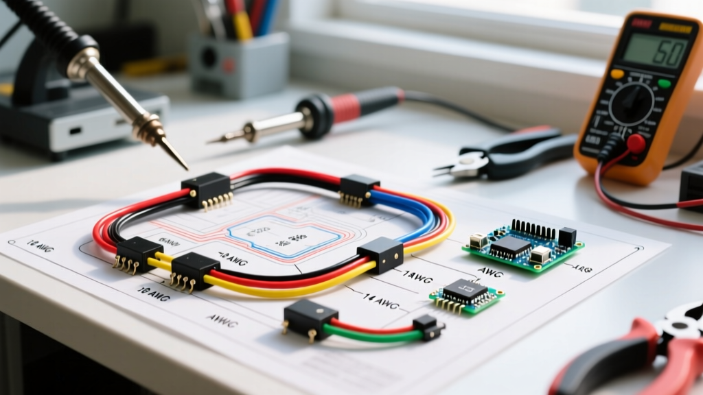

Decoding the Wiring Diagram for Scooter Systems
Whether you are restoring a classic Vespa GTS 300, troubleshooting a generic GY6 50cc 4-stroke clone, or upgrading the battery harness on a 72V Segway Ninebot electric scooter, relying on a generic automotive wiring approach will lead to catastrophic failures. Scooters operate in high-vibration, high-heat, and moisture-prone environments. Understanding the exact wiring diagram for scooter applications requires a deep dive into specific DC voltage drop tolerances, American Wire Gauge (AWG) sizing, and manufacturer-specific color codes.
This reference guide bridges the gap between factory service manuals and real-world garage diagnostics, providing the exact wire gauge matrices and color code standards used by professional scooter technicians in 2026.
Anatomy of Scooter Electrical Architectures
Before selecting wire gauges, you must understand the two primary electrical architectures found in modern scooters. Internal Combustion Engine (ICE) scooters typically utilize a 12V DC system powered by a stator, regulator/rectifier, and a small 12V lead-acid or lithium-iron-phosphate (LiFePO4) battery. Electric scooters (e-scooters) operate on high-voltage DC systems ranging from 36V to 72V, utilizing brushless DC (BLDC) hub motors, electronic speed controllers (ESC), and battery management systems (BMS).
Expert Insight: Never use standard PVC-jacketed household wire (THHN) for any scooter application. Scooters require flexible, multi-strand wire with high-temperature cross-linked insulation (TXL or GXL) for ICE models, and high-temperature silicone jacketing for e-scooter phase wires.
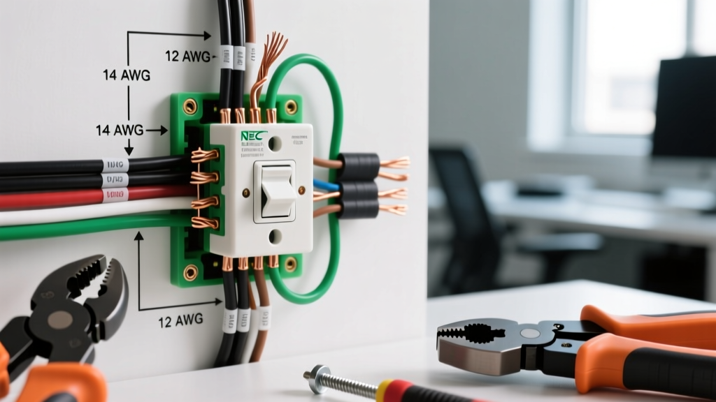
Wire Gauge (AWG) Selection Matrix
Voltage drop is the silent killer of scooter performance. A 12V headlight circuit experiencing a 1.5V drop due to undersized wiring will output significantly less lumens and cause the stator to overwork. For high-amperage e-scooter phase wires, undersized gauge leads to insulation meltdown and ESC failure. The following matrix is based on standard DC ampacity limits and Blue Sea Systems DC circuit sizing standards, adapted for the short-run, high-vibration environment of scooters.
| Circuit Type | Peak Amp Draw | Recommended AWG | Wire Insulation Type | Voltage Drop Limit |
|---|---|---|---|---|
| Starter Motor (ICE 150cc-300cc) | 80A - 150A | 4 AWG to 2 AWG | Cross-Linked (GXL/SXL) | < 0.5V |
| Starter Relay to Solenoid | 2A - 5A | 14 AWG | TXL (Thin Cross-Link) | < 0.2V |
| Stator to Regulator/Rectifier (AC) | 15A - 25A | 12 AWG | High-Temp Fiberglass/Silicone | N/A (AC Output) |
| Headlight (Halogen H4) | 8A - 10A | 14 AWG | TXL / GXL | < 0.3V |
| Headlight (LED Upgrade) | 2A - 3A | 18 AWG | TXL | < 0.2V |
| ECU / CDI / Fuel Injection | 1A - 3A | 18 AWG to 20 AWG | TXL | < 0.1V |
| E-Scooter Battery to ESC (36V-72V) | 30A - 80A | 8 AWG to 6 AWG | Silicone (200°C rated) | < 1.0V |
| E-Scooter Phase Wires (U, V, W) | 40A - 100A+ | 10 AWG to 8 AWG | Silicone (200°C rated) | N/A (AC Pulse) |
| E-Scooter Hall Sensors / Throttle | < 0.5A | 22 AWG to 24 AWG | Silicone / PVC (Shielded) | N/A (Signal) |
Note: For runs exceeding 4 feet (common in long-wheelbase maxi-scooters like the Yamaha XMAX or Honda ADV350), increase the wire gauge by one step (e.g., move from 14 AWG to 12 AWG) to compensate for resistance over distance. Refer to DC voltage drop calculation guides for exact long-run math.
Standard Color Code References
Unlike automotive standards (SAE J1128) which have strict color mandates, scooter wiring diagrams often rely on legacy manufacturer codes or generic Chinese import standards. Below are the definitive color code references for the two most common scooter platforms.
1. ICE Scooters (Honda / Yamaha / GY6 Clones)
The GY6 engine platform powers roughly 70% of the world's 50cc to 150cc scooters. If you are reading a wiring diagram for scooter models from Roketa, TaoTao, or genuine Honda/Yamaha variants, expect these core colors:
- Green or Green/White: System Ground (Chassis/Battery Negative).
- Red: Battery Positive (Unswitched 12V from battery to main fuse).
- Black: Switched 12V Positive (Power after the ignition key switch).
- Yellow: AC Power from Stator (Pre-rectifier, goes directly to headlight on some older AC-headlight models, or to the regulator).
- White: AC Power from Stator (Dedicated to the regulator/rectifier for battery charging).
- Black/Red: CDI Kill Switch / Ignition Coil Ground (Shorting this to ground kills the engine).
- Blue/White: Pickup Coil / Trigger Signal (Sends RPM timing data to the CDI).
- Pink or Pink/White: Ignition Coil Positive (High voltage trigger).
2. Electric Scooters (Xiaomi, Ninebot, Generic BLDC Hubs)
E-scooter wiring diagrams prioritize high-voltage safety and signal integrity. The U.S. Department of Energy's e-mobility guidelines emphasize strict adherence to DC polarity coloring to prevent catastrophic ESC short-circuits.
- Thick Red: Main Battery Positive (B+).
- Thick Black: Main Battery Negative (B-).
- Thick Yellow, Green, Blue: Motor Phase Wires (U, V, W). Never swap these, or the motor will stutter, overheat, and potentially destroy the ESC MOSFETs.
- Thin Red: Hall Sensor 5V Power.
- Thin Black: Hall Sensor Ground.
- Thin Yellow, Green, Blue: Hall Sensor Signals (must match the corresponding Phase wire colors).
- Thin White/Green: Throttle Signal (Usually 0.8V to 4.2V analog return).
- Orange: BMS Communication Line (TX/RX for Bluetooth telemetry).
Critical Failure Modes & Edge Cases
When diagnosing a faulty wiring diagram for scooter setups, technicians frequently encounter three specific failure modes that are rarely documented in factory manuals.
The Steering Stem Chafe Point
On both ICE and e-scooters, the main wiring harness must pass through or around the steering stem to reach the handlebar controls, headlight, and display. Over time, the constant left-right articulation wears through the outer loom tape and wire insulation. Edge Case: On the Honda PCX and ADV150, the harness rubs against the internal steel steering stop. If the 12V switched black wire chafes against the grounded steel frame, it will blow the main 15A fuse instantly. Fix: Always wrap the steering stem harness segment in split-loom corrugated tubing lined with friction tape (Tesa 51036 PET cloth tape), never standard vinyl electrical tape which turns into a sticky mess in summer heat.
E-Scooter Phase Wire Meltdown
Many budget e-scooters use 12 AWG PVC-insulated wire for the phase wires connecting the ESC to the hub motor. Under heavy load (e.g., climbing a 15% grade), phase current can spike to 80A+. PVC insulation begins to soften and melt at 105°C. The melted insulation allows the U, V, and W phase wires to short together inside the swingarm, instantly frying the ESC. Fix: When rebuilding an e-scooter harness, always cut back the factory phase wires and solder on 10 AWG or 8 AWG high-temperature silicone wire, which withstands up to 200°C.
Undersized Factory Grounds on 50cc Scooters
To save copper costs, many import 50cc scooters use 16 AWG or 18 AWG wire for the main engine-to-frame ground strap. When owners upgrade to a 60W halogen headlight or add auxiliary LED fog lights, the voltage drop across this thin ground wire causes the taillight to pulse with engine RPMs and the battery to undercharge. Fix: Run a dedicated 10 AWG ground wire directly from the battery negative terminal to the engine crankcase mounting bolt.
Step-by-Step: Tracing a No-Start Fault Using the Diagram
When a GY6-based ICE scooter cranks but will not start, use the wiring diagram to isolate the ignition circuit systematically:
- Verify the Kill Switch Circuit: Locate the Black/White wire on the CDI. With the key ON and the run switch engaged, use a multimeter to check for continuity to ground. There should be no continuity. If there is, your kill switch or sidestand safety switch is shorted to ground.
- Test the Stator Trigger: Back-probe the Blue/White wire at the CDI connector. Set your multimeter to AC Volts. Kick the engine over. You should see a momentary spike of 1.5V to 4.0V AC. If it reads 0V, the stator pickup coil is dead or the air gap is too wide (spec is typically 0.4mm - 0.6mm).
- Check the Coil Primary: Verify 12V DC is reaching the ignition coil via the Black (switched) wire while cranking. If voltage drops below 10V during cranking, your starter motor is drawing too much current due to a weak battery or corroded starter cables, starving the CDI of operating voltage.
Final Best Practices for 2026 Repairs
Modern scooters are increasingly reliant on CAN-bus networks and LIN-bus communication, especially in premium models like the BMW C 400 GT or the Vespa GTS 300 Tech Edition. When repairing data lines, never use standard crimp connectors or solder joints that alter the wire's impedance. Always use factory-spec Deutsch or Sumitomo sealed connectors, and ensure shielded twisted-pair (STP) wiring is used for any sensor or communication lines to prevent electromagnetic interference (EMI) from the high-voltage stator or ESC.
By strictly adhering to proper AWG sizing, utilizing high-temperature insulation, and respecting manufacturer color codes, you ensure the electrical system of your scooter remains reliable, safe, and optimized for the road ahead.