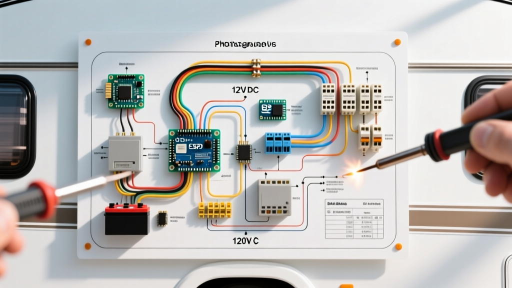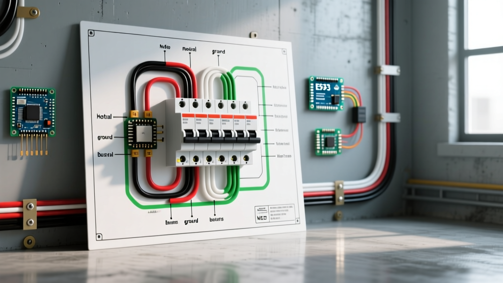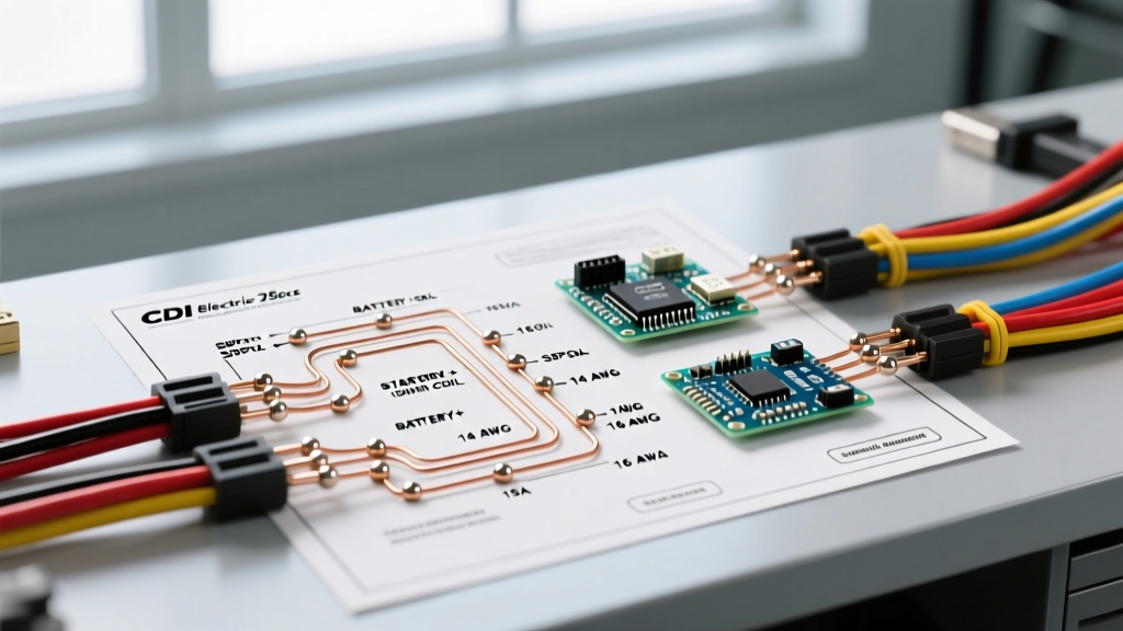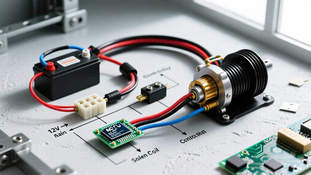

Anatomy of a 12V ATV Winch Circuit
Installing a winch on your ATV or UTV is one of the most practical upgrades for off-road recovery, but the electrical demands of a 12V DC winch motor are massive. Under maximum load, a standard 3,000 lb to 4,500 lb ATV winch can draw anywhere from 150 to 300 amps. This is why relying on the factory stator or a basic handlebar rocker switch to carry the primary current is a recipe for melted wires and electrical fires. A proper wiring diagram for ATV winch setups always isolates the high-amperage motor circuit from the low-amperage control circuit using a heavy-duty contactor (solenoid).
In this comprehensive reference guide, we break down the exact node-to-node routing, wire gauge requirements, and critical failure points associated with modern ATV winch installations. Whether you are wiring a Warn Vantage 3000, a Superwinch Terra 45, or a budget-friendly Champion kit, the underlying 12V DC principles remain identical.
The 4-Post vs. 2-Post Contactor Dilemma
Before tracing the diagram, you must identify your contactor type. As of 2026, the market is split between two primary solenoid designs:
- 2-Post Solenoids (Chassis Ground): Common in budget winch kits. The motor ground is routed directly to the ATV frame, and the solenoid only switches the positive feed. This requires a flawless, bare-metal frame ground. If your ATV has a powder-coated frame or composite skid plates, this setup will fail.
- 4-Post Solenoids (Isolated Ground): The industry standard for premium brands like Warn Industries. Both the positive and negative motor cables run back to the solenoid, keeping the high-amperage ground path entirely independent of the vehicle chassis. This is the configuration detailed in our primary diagram below.
Node-to-Node Wiring Diagram Reference
Because visual schematics can be difficult to read on mobile devices in the garage, we have translated the standard 4-post wiring diagram for ATV winch systems into a precise node-routing map. This assumes the use of a marine-grade circuit breaker and a 4-post continuous-duty solenoid.
High-Amperage Circuit (The Power Path)
- Battery Positive (+) → Circuit Breaker (Input): Run a primary positive cable from the battery terminal to the input stud of a 150A-250A marine breaker.
- Circuit Breaker (Output) → Solenoid Post A (Large): Route the protected positive cable to one of the large copper studs on the contactor.
- Solenoid Post B (Large) → Winch Motor Positive (+): Run the second heavy-gauge positive cable from the opposite large stud down to the winch motor's positive terminal.
- Winch Motor Negative (-) → Solenoid Post C (Large): Run the motor's ground cable back up to a third large stud on the contactor (if using a dedicated ground bridge) OR directly to the Battery Negative (-) terminal. Note: Many 4-post ATV solenoids internally bridge the two large posts on each side. Always consult your specific contactor's continuity map.
- Solenoid Ground Bridge → Battery Negative (-): Complete the high-amp circuit by tying the solenoid's ground lug directly to the battery negative terminal, bypassing the chassis entirely.
Low-Amperage Circuit (The Control Path)
- Ignition/Accessory 12V Source → Rocker Switch / Wireless Receiver: Tap into a switched 12V source (like the accessory bus or keyed ignition) using an add-a-circuit fuse tap (10A fuse).
- Switch Output → Solenoid Spade Terminal 1 (Small): When the switch is pressed 'IN', it sends 12V to the first small spade terminal, energizing the internal coil.
- Solenoid Spade Terminal 2 (Small) → Chassis Ground: The second small spade terminal completes the control circuit by grounding to a clean, bare-metal point on the ATV frame.
Wire Gauge & Amperage Selection Matrix
According to standards outlined by the Society of Automotive Engineers (SAE) and marine electrical guidelines from Blue Sea Systems, DC wire gauge must be sized based on maximum amperage draw and the total length of the wire run (round-trip). ATV winches experience extreme voltage drop due to the long run from the front bumper to the rear-mounted battery.
| Winch Capacity | Max Amp Draw (Stall) | Recommended Wire Gauge (Up to 10ft Run) | Recommended Wire Gauge (10ft - 15ft Run) | Breaker Size |
|---|---|---|---|---|
| 2,000 - 3,000 lbs | 120A - 180A | 4 AWG | 2 AWG | 150A |
| 3,500 - 4,500 lbs | 180A - 250A | 2 AWG | 1/0 AWG | 200A |
| 5,000+ lbs (UTV) | 250A - 350A+ | 1/0 AWG | 2/0 AWG | 250A - 300A |
Critical Expert Tip: Never use Copper-Clad Aluminum (CCA) wire for winch battery cables. CCA has a 30% higher electrical resistance than pure OFC (Oxygen-Free Copper) and will overheat rapidly under the sustained 200A+ loads of a stalled winch motor. Always verify your cables are stamped "OFC" or "AWG Pure Copper".
Step-by-Step Execution & Pro Techniques
Having the correct wiring diagram for ATV winch setups is only half the battle. Execution dictates longevity. Here is the professional workflow for terminating and routing your cables.
1. Terminal Crimping and Sealing
Do not use standard automotive wire crimpers for 4 AWG or 2 AWG battery cables. You must use a hex-crimp die tool (such as the IWISS IWS-16 or a hydraulic crimper). Hex crimps provide a 360-degree cold weld that prevents the terminal from pulling out under vibration. After crimping, seal the terminal barrel with adhesive-lined dual-wall heat shrink (3:1 shrink ratio). When heated, the inner meltable adhesive pushes out the ends, creating a waterproof seal that prevents battery acid wicking and green corrosion.
2. Thermal and Mechanical Routing
Route all high-amperage cables away from the CV joints, steering shafts, and exhaust headers. On modern ATVs with tight plastic cowls, use split-loom corrugated tubing and secure the loom with UV-resistant nylon zip ties every 6 inches. If a cable must pass through a metal bulkhead or frame rail, install a rubber grommet and apply a dab of silicone RTV sealant to prevent chafing and short circuits.
3. The Ground Point Preparation
If your control circuit requires a chassis ground, do not simply bolt it to painted metal. Use a flap disc or sandpaper to remove the paint, powder coat, or rust down to bare, shiny metal. Apply the ring terminal, torque it to the manufacturer's specification (usually 8-12 ft-lbs for M6 bolts), and immediately coat the entire connection in Noalox or a heavy dielectric grease to prevent galvanic corrosion.
Common Failure Modes & Troubleshooting
Even with a perfect wiring diagram for ATV winch installations, environmental factors and component fatigue can cause issues. Here is how to diagnose the most common edge cases:
- Symptom: Solenoid clicks rapidly, but motor does not turn.
Diagnosis: This is almost always a severe voltage drop. The control circuit has enough power to pull the solenoid plunger, but the high-amp contacts are pitted, corroded, or the battery is depleted. Load-test the battery and check the large copper studs on the solenoid for heat discoloration. - Symptom: Winch spools in, but will not spool out (or vice versa).
Diagnosis: If using a 4-post solenoid, one of the internal directional contact plates has likely welded itself shut or failed to make contact. If using a 2-post solenoid with a motor-ground-through-chassis setup, inspect the motor ground strap for frame rust. - Symptom: Circuit breaker trips immediately under load.
Diagnosis: You may have an undersized breaker, or the winch motor is seizing. Disconnect the motor and spin the drum by hand. If it binds, the internal planetary gears may lack lubrication or the brake mechanism is corroded.
Final Safety and Maintenance Directives
Always install a heavy-duty battery disconnect switch or a secondary cutoff relay if your ATV will be stored for more than 30 days. A parasitic draw from a wireless winch receiver or a micro-short in the handlebar switch can drain an AGM or Lithium battery to the point of irreversible sulfation or BMS lockout. Furthermore, inspect all winch wiring connections at the start of every riding season, retorquing the solenoid nuts to 10 ft-lbs to compensate for thermal expansion and contraction cycles. By adhering strictly to this wiring diagram for ATV winch systems and utilizing marine-grade components, your recovery setup will deliver reliable, high-torque performance for years to come.