
Introduction to Shunt Trip Breakers in Appliance Systems
When integrating heavy commercial appliances, industrial HVAC systems, or kitchen exhaust setups with emergency safety protocols, a standard breaker is not enough. You need a remote disconnect mechanism. This is where understanding a wiring diagram for shunt trip circuit breaker configurations becomes critical. A shunt trip is an optional accessory module that attaches to the side or bottom of a standard molded case circuit breaker (MCCB). When a specific control voltage is applied to the shunt trip coil, it generates a magnetic field that pulls a plunger, mechanically forcing the breaker's internal trip bar to open the circuit.
In 2026, modern commercial appliance setups—such as industrial convection ovens, commercial makeup air units, and automated fryer batteries—rely heavily on these systems to ensure immediate power cutoff during fire events or emergency stop (E-Stop) activations. This guide breaks down the exact wiring topology, component selection, and edge-case troubleshooting required to wire these systems safely and in compliance with current electrical codes.
CRITICAL SAFETY WARNING: Shunt trip coils are typically designed for intermittent duty. If the control circuit remains energized after the breaker trips, the coil will overheat and vaporize within seconds. Always incorporate an auxiliary normally-closed (NC) contact or a momentary trigger in your wiring design.
Core Components of the Wiring Diagram
Before routing wires, you must identify the four primary nodes in any shunt trip wiring diagram:
- The Main Breaker: The primary overcurrent protection device (e.g., Eaton BR250ST or Square D QO250STM8). In 2026, expect to pay between $135 and $175 for a 50-Amp 2-pole unit with a factory-installed shunt module.
- The Shunt Trip Coil (C1 & C2): The solenoid accessory. Terminals are usually labeled C1 and C2. These terminals are non-polarized for AC coils but strictly polarized for DC coils.
- The Trigger Device: The appliance safety relay, Ansul fire suppression microswitch, or E-Stop push-button that initiates the trip signal.
- The Control Power Source: An independent voltage source (often 120V AC or 24V DC) that feeds the coil when the trigger device closes.
Appliance Scenario: Commercial Kitchen Fire Suppression Integration
Let us apply the wiring diagram for shunt trip circuit breaker logic to a real-world scenario: integrating a commercial kitchen hood fire suppression system (like an Ansul R-102) with a 5-horsepower makeup air unit. According to NFPA 96 standards, when a fire suppression system discharges, it must automatically shut down all power and fuel sources to the cooking appliances and exhaust fans.
Step 1: Matching Coil Voltage to Control Circuit
The most common failure in DIY and junior electrician installations is voltage mismatch. The shunt trip coil must exactly match the voltage of your fire alarm or appliance control board relay.
| Control Source | Required Coil Suffix (Eaton BR) | Wire Gauge (THHN) | Max Run Distance |
|---|---|---|---|
| 120V AC Panel | ST (120/240V AC) | 14 AWG | 250 ft |
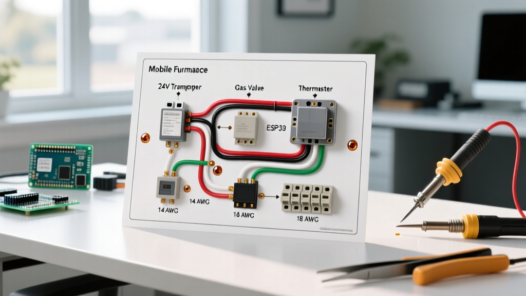
| 24V DC Appliance Board | STL (24V DC) | 18 AWG | 50 ft |
| 208V AC 3-Phase | ST (208V AC) | 14 AWG | 300 ft |
Step 2: Routing the Control Wiring
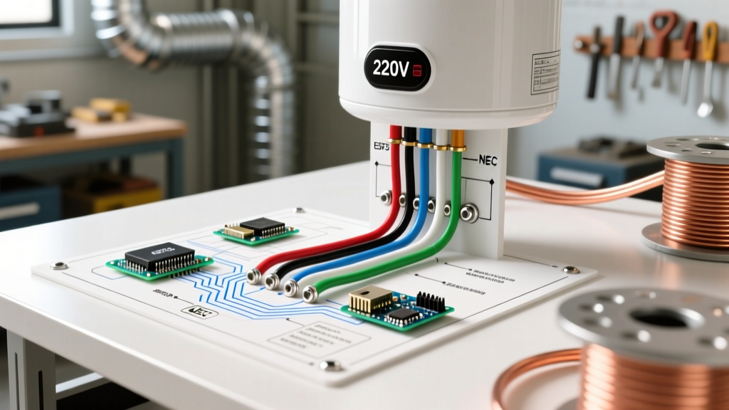
When wiring a commercial appliance shutdown, the control wires (C1 and C2) must be routed through a dedicated knockout on the panel. Do not run 24V DC control wires in the same conduit as 480V 3-phase appliance feed lines to prevent electromagnetic interference (EMI) and induction heating. Use separate conduits or a physical barrier as mandated by NEC Article 300.
Step 3: Terminating at the Breaker and Relay
- Turn off the main service disconnect and verify zero energy using a CAT IV multimeter. Follow OSHA electrical safety guidelines for lockout/tagout (LOTO) procedures.
- Connect the C1 terminal of the shunt trip coil to the Line Side (or an independent control power source) via the fire relay's Normally Open (NO) contact.
- Connect the C2 terminal to the Neutral or DC ground return path.
- Torque the control wire terminal screws to the manufacturer's specification—typically 40 to 50 in-lbs for 14 AWG wire on modern Eaton and Square D breakers.
Advanced Wiring Configurations & Information Gain
A standard wiring diagram for shunt trip circuit breaker setups often misses a vital component: the auxiliary switch. If you are wiring an E-Stop button on an industrial dough mixer or packaging appliance, the operator might push the button (closing the circuit), tripping the breaker. If the button remains physically locked in the 'pressed' position, voltage continues to flow to the shunt coil.
The 'Burned Coil' Prevention Circuit
To prevent coil burnout, you must wire a Normally Closed (NC) auxiliary contact (such as the Eaton BRA1SW module) in series with the shunt trip coil.
- How it works: The auxiliary switch is mechanically tied to the breaker's toggle. When the breaker is ON, the NC contact is closed, allowing the trip circuit to stand by. The millisecond the breaker trips, the toggle moves, opening the NC contact and instantly dropping voltage from the shunt coil—even if the fire relay or E-Stop button remains closed.
- Cost Impact: Adding an auxiliary switch module costs roughly $45 to $60 in 2026, but it saves a $150 breaker from catastrophic failure and ensures the system can be safely reset without replacing the shunt module.
Troubleshooting Common Edge Cases
Even with a perfect wiring diagram, field conditions introduce variables. Here is how to troubleshoot specific failure modes:
1. Breaker Trips Instantly Upon Reset
Cause: The trigger device (e.g., fire alarm relay) has not reset and is still sending voltage to C1/C2. Alternatively, the coil has shorted internally due to a previous over-voltage event.
Fix: Isolate the control wires from C1 and C2. Attempt to reset the breaker. If it holds, the fault is in the appliance control board or fire relay. If it still trips immediately, the shunt trip plunger is jammed, or the coil is shorted. Replace the accessory module.
2. Relay Clicks, but Breaker Does Not Trip
Cause: Voltage drop across the control wire run. If you used 18 AWG wire for a 24V DC coil over a 75-foot run to a rooftop HVAC appliance, the voltage at C1/C2 may have dropped below 18V, which is insufficient to pull the solenoid plunger.
Fix: Measure voltage at the coil terminals during the trigger event. Upgrade control wiring to 14 AWG or move the control power transformer closer to the panel.
NEC & Safety Code Compliance
When integrating these diagrams into building infrastructure, compliance is non-negotiable. According to the National Electrical Code (NEC), shunt trip wiring must be treated as a control circuit. If the control circuit originates from a different panel than the breaker it is tripping, it must be clearly labeled at both ends. Furthermore, for fire pump and life-safety appliance circuits, NEC Article 695 strictly prohibits the use of shunt trip breakers on the main fire pump feed, as these circuits must remain energized to fight the fire. Always consult the latest Eaton circuit protection documentation or local AHJ (Authority Having Jurisdiction) before finalizing commercial appliance schematics.
Frequently Asked Questions
Can I wire the shunt trip coil to the load side of its own breaker?
Technically, yes, but it is highly discouraged for appliance safety circuits. If wired to the load side, the coil loses power the moment the breaker trips. While this prevents coil burnout, it means the system cannot be tested easily without resetting the breaker, and it violates the principle of independent disconnect verification required by many commercial insurance underwriters.
Do 24V DC shunt trip coils have polarity?
Yes. Unlike 120V AC coils, 24V DC coils are polarized. C1 must connect to the positive (+) DC voltage, and C2 must connect to the negative (-) or ground return. Reversing the polarity on certain modern solid-state shunt modules will blow the internal protection diode, rendering the trip mechanism useless.
What is the response time of a shunt trip breaker?
Once the rated voltage is applied to C1/C2, the solenoid pulls the plunger in approximately 15 to 30 milliseconds. The breaker's mechanical linkage then opens the contacts within another 15 to 20 milliseconds. Total clearing time from relay closure to arc extinction is typically under 50 milliseconds, providing instantaneous protection for sensitive commercial appliance electronics.