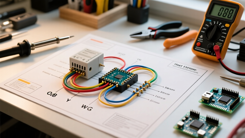

Mastering Heat Pump Control Logic: A Troubleshooting Guide
Unlike conventional gas furnaces or standard air conditioners, heat pumps move thermal energy rather than generating it directly. This fundamental difference requires a more complex control sequence, primarily managed by the reversing valve and auxiliary heating elements. When an HVAC system fails to transition between heating and cooling, or when auxiliary strips short-cycle, the root cause is almost always found by cross-referencing the physical wiring with the schematic. Understanding how to read and troubleshoot a wiring diagram for thermostat with heat pump configurations is the most critical skill for any DIY electronics enthusiast or HVAC technician.
In this comprehensive guide, we will decode standard heat pump schematics, isolate specific terminal failures using a multimeter, and address modern smart thermostat integration issues. According to the U.S. Department of Energy, proper installation and control wiring are paramount to achieving the high SEER2 and HSPF2 efficiency ratings modern heat pumps promise.
Decoding the Diagram: Heat Pump vs. Conventional Terminals
A standard 5-wire AC/Gas setup uses R, W, Y, G, and C. A heat pump system expands this to accommodate the reversing valve and multi-stage backup heat. When examining your wiring diagram, you will encounter the following critical terminals:
- R (or Rc/Rh): 24VAC hot power from the air handler's step-down transformer.
- Y (or Y1): Compressor contactor coil. Energizes the outdoor unit for cooling and defrost cycles.
- G: Indoor blower fan relay. Runs the fan independently or in tandem with Y/W.
- W (or W1/Aux): Auxiliary heat. Triggers the electric heat strips or gas backup when the heat pump cannot meet the heating load.
- E: Emergency heat. Bypasses the outdoor heat pump entirely and forces the system to run strictly on backup heat strips.
- C: Common wire. Completes the 24VAC circuit, essential for smart thermostats and continuous logic boards.
The O/B Reversing Valve Dilemma
The most common point of failure when migrating to a new thermostat or troubleshooting a newly installed heat pump is the reversing valve terminal, labeled as O/B or split into separate O and B terminals on advanced diagrams. The reversing valve physically shifts the flow of refrigerant to determine whether the indoor coil acts as an evaporator (cooling) or condenser (heating).
Expert Insight: The majority of manufacturers (Carrier, Trane, Lennox, Mitsubishi) energize the O terminal during the cooling cycle. However, Rheem, Ruud, and Goodman systems typically energize the B terminal during the heating cycle. If your wiring diagram is misinterpreted and the valve is wired or configured incorrectly, the system will blow hot air in cooling mode and cold air in heating mode.
Auxiliary vs. Emergency Heat (W2 vs. E)
Many homeowners and junior technicians confuse W2 (Auxiliary) with E (Emergency). On a proper wiring diagram, W2 is controlled by the thermostat's algorithms based on outdoor temperature drops or defrost cycles. The E terminal is a manual override. If your diagram shows the E terminal wired to the primary heat strip sequencer instead of a dedicated lockout relay, engaging Emergency Heat will prematurely age your contactors and spike your electricity bill, as noted in efficiency guidelines by EPA ENERGY STAR.
Step-by-Step Troubleshooting Using Your Wiring Diagram
When a system malfunctions, do not guess. Use the wiring diagram to trace the voltage drops. You will need a digital multimeter set to VAC (Volts Alternating Current) and a nut driver to remove the air handler access panels.
Step 1: Verify the 24VAC Power and Common Circuit
Before testing individual functions, confirm your control voltage. Place your multimeter probes on the R and C terminals at the air handler control board. You should read between 24VAC and 28VAC. If you read 0V, check the 3A or 5A ATO automotive-style blade fuse located on the control board. A blown fuse usually indicates a short circuit in the thermostat wire (often caused by a weed whacker damaging the outdoor low-voltage bundle).
Step 2: Isolate the Reversing Valve Circuit
If the system is blowing warm air in AC mode:
- Set the thermostat to Cool and drop the temperature below the room ambient.
- Measure voltage between C and the O terminal at the outdoor unit's contactor board. You should see 24VAC.
- If you have 24VAC but the valve hasn't shifted (indicated by a lack of a loud 'swoosh' sound and warm air from indoor registers), the valve solenoid coil is likely burnt out (typically 12-18 ohms resistance). Replace the solenoid ($25-$45 part).
- If you have 0VAC at O, trace the diagram back to the thermostat. Ensure the wire is seated in O, not B (for non-Rheem systems).
Step 3: Diagnosing Auxiliary Heat Engagement
If the heat pump runs constantly in freezing weather but the house remains cold, the auxiliary strips may not be engaging. Trace the W2 wire on your diagram to the heat strip sequencer. When the thermostat calls for Aux, it sends 24VAC to the sequencer coil. The sequencer then closes the line-voltage contacts (240V) to power the nichrome heating elements. Use a non-contact voltage tester or a high-voltage multimeter to verify 240V at the sequencer output when W2 is energized.
Diagnostic Matrix: Symptoms, Terminals, and Multimeter Tests
Use this troubleshooting matrix to quickly map physical symptoms to diagram checkpoints.
| Symptom | Suspect Terminals | Multimeter Test (VAC) | Resolution & Diagram Action |
|---|---|---|---|
| Blows hot air in Cool mode | O / B | Check R to O (should be 24V in Cool) | Move wire from B to O (or vice versa for Rheem/Ruud). Update thermostat UI settings. |
| Blower runs continuously | G / R | Check R to G (should be 0V when fan is Auto) | Check for short between G and R wires in the wall cavity or at the subbase. |
| No heating, but outdoor fan runs | Y / W | Check R to W (should be 24V in Heat) | Y might be crossed with W. Re-verify diagram pinouts at both the stat and control board. |
| Short cycling in Heat mode | Y / Defrost Board | Check Defrost board Y-to-C output | Defrost thermostat or sensor may be failing, sending erratic signals back through the diagram's Y path. |
Smart Thermostat Upgrades: Adapter and C-Wire Troubleshooting
Upgrading to a modern smart thermostat like the Ecobee SmartThermostat Premium ($249) or the Nest Learning Thermostat 4th Gen ($279) often exposes missing C-wires in older homes. A wiring diagram for a thermostat with a heat pump setup strictly requires a C-wire to power the Wi-Fi radios and advanced sensors without 'power stealing' from the Y or W terminals, which can cause the outdoor contactor to chatter or the reversing valve to drop out mid-cycle.
If your diagram lacks a C-wire connection at the thermostat plate, you have two code-compliant solutions:
- Run a new 18/5 or 18/8 thermostat cable: This is the gold standard. Connect the unused 5th wire to the C terminal on the air handler control board and the C terminal on the thermostat.
- Install a Power Extender Kit (PEK) or C-Wire Adapter: Devices like the Nest Power Connector (Model GA02405-US, ~$39) wire directly into the air handler control board, multiplexing the 24VAC power and data signals over the existing 4 wires, effectively creating a virtual C-wire.
Safety Protocols and NEC Code Compliance
While the thermostat circuit operates at a relatively safe 24VAC, the air handler and outdoor condenser contain lethal line voltages (240V). Always shut off the main disconnect breaker at the outdoor unit and the dedicated breaker for the indoor air handler before removing access panels to trace wiring diagrams.
Furthermore, adhere to the National Electrical Code (NEC) Article 725 regarding Class 1 and Class 2 remote-control and signaling circuits. Never run 24VAC thermostat wires in the same conduit or wall cavity hole as 120V/240V line-voltage wiring without a physical barrier, as electromagnetic interference can cause erratic heat pump behavior and poses a severe shock hazard if insulation degrades.
By meticulously following your system's specific wiring diagram and utilizing a multimeter to verify voltage at each node, you can resolve 95% of heat pump control issues without relying on guesswork or unnecessary component replacements.