
Mastering the Wiring Diagram for Outside Light: Gauge, Color Codes, and NEC Compliance
Designing and executing a reliable wiring diagram for outside light installations requires more than just connecting a switch to a fixture. Exterior electrical circuits are subjected to extreme temperature fluctuations, moisture ingress, and physical damage risks. As of 2026, with the widespread adoption of the latest National Electrical Code (NEC) standards and the stabilization of copper prices around $4.15 per pound, electricians and advanced DIYers must carefully balance material costs with strict ampacity and voltage drop requirements.
This comprehensive reference guide breaks down the exact wire gauge selections, NEC-mandated color codes, and burial specifications required to build a safe, code-compliant outdoor lighting circuit. Whether you are wiring a simple porch sconce, a multi-fixture driveway path, or a high-draw security floodlight, understanding the underlying physics and code requirements is non-negotiable.
Deconstructing the Basic Wiring Diagram for Outside Light
Before selecting your cable, you must define the circuit topology. The most common and code-compliant wiring diagram for outside light setups involves routing power from the main service panel to an interior or weatherproof exterior switch, and then to the light fixture.
Power-to-Switch vs. Power-to-Fixture Topologies
- Power-to-Switch (Preferred): The 120V feed enters the switch box first. A 2-wire (or 3-wire for smart switches) cable runs from the switch to the exterior fixture. This topology is preferred because it keeps the line voltage contained within the switch box, making fixture replacements safer since the exterior cable is only energized when the switch is closed.
- Power-to-Fixture (Switch Loop): The 120V feed enters the exterior fixture box first, and a 2-wire cable drops down to the switch. Under current NEC Article 404.2(C), switch loops must include a grounded (neutral) conductor, meaning you must use a 3-wire cable (Black, Red, White) even if the neutral isn't used at the switch, to accommodate future smart switches or photocells.
NEC Color Code Mandates for Exterior Wiring
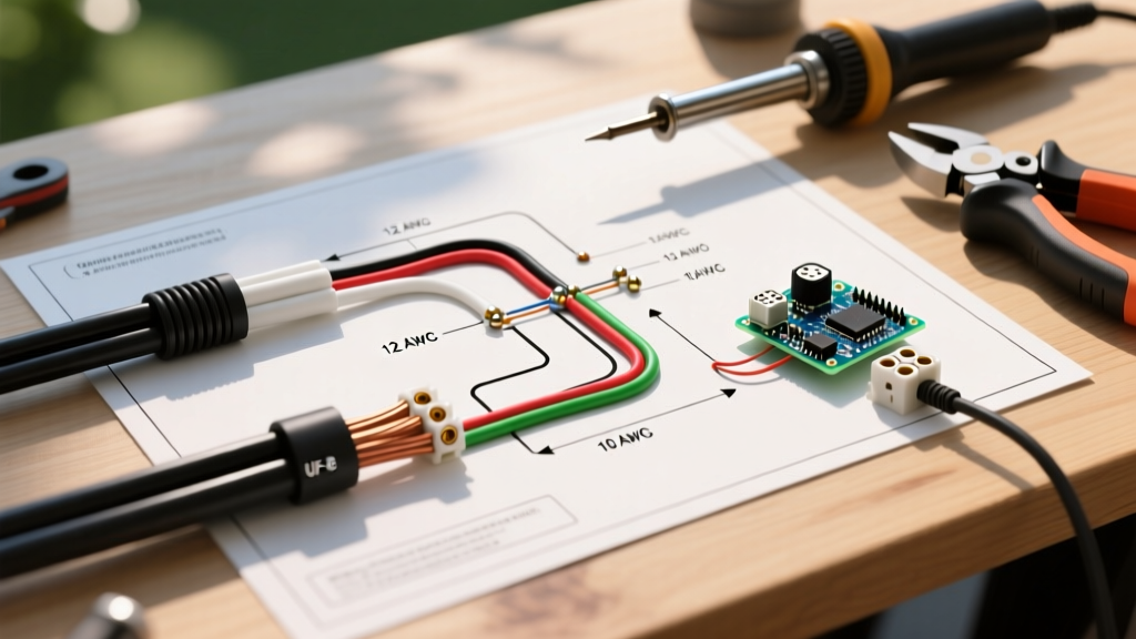
Adhering to standardized color codes is critical for safety and future troubleshooting. When pulling individual THWN-2 conductors through exterior PVC conduit, or when using jacketed UF-B (Underground Feeder) cable, the following color designations apply to 120V/240V residential circuits.
| Conductor Function | NEC Mandated Color (THWN-2 in Conduit) | UF-B Cable Jacket/Insulation Color | NEC Article Reference |
|---|---|---|---|
| Ungrounded (Hot / Line) | Black, Red, or Blue | Black (or Red for 240V/Switch Leg) | 200.7 / 310.12 |
| Grounded (Neutral) | White or Gray | White | 200.2 / 210.5 |
| Equipment Grounding | Bare, Green, or Green/Yellow Stripe | Bare Copper | 250.118 / 210.5 |
| Switched Hot (Load) | Red or Black (taped) | Red (in 3-wire UF-B) | 404.2 |
Expert Insight: Never use a white wire as a hot conductor in a UF-B cable run to an outside light unless it is permanently re-identified with black electrical tape or heat shrink at both termination points, as per NEC 200.7(C)(1). Failing to do so is a leading cause of electrical shocks during future fixture replacements.
Wire Gauge Selection: Calculating Ampacity and Voltage Drop
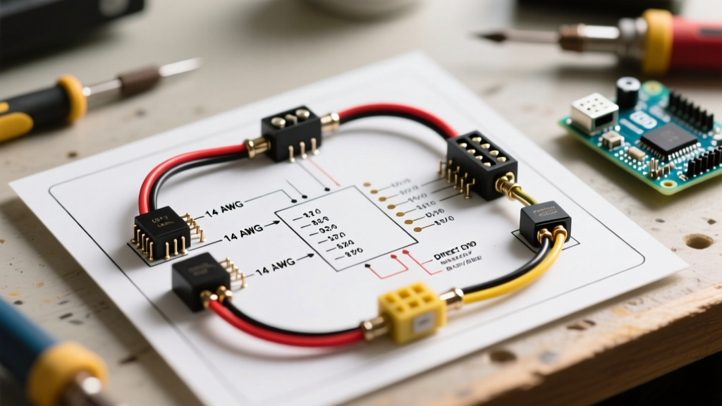
Selecting the correct American Wire Gauge (AWG) is the most mathematically rigorous part of your wiring diagram for outside light. While a standard 15-amp interior circuit uses 14 AWG copper, exterior runs often span long distances across yards, introducing voltage drop. The NEC recommends a maximum voltage drop of 3% for branch circuits to ensure optimal performance and longevity of LED drivers and halogen transformers.
With modern LED fixtures drawing minimal current (often under 0.2 amps per fixture), voltage drop is less about thermal ampacity and more about maintaining sufficient voltage at the furthest fixture to prevent flickering or premature driver failure.
AWG Sizing Matrix for 120V Exterior Lighting Runs
The following table assumes a standard 120V single-phase circuit, a maximum 3% voltage drop (3.6V), and a cumulative LED load of 300 Watts (2.5 Amps). Always calculate based on the maximum anticipated load, including future expansions.
| One-Way Run Distance | 14 AWG Copper (Max 15A) | 12 AWG Copper (Max 20A) | 10 AWG Copper (Max 30A) | Recommended Application |
|---|---|---|---|---|
| Under 50 Feet | Safe (Drop < 1%) | Safe (Drop < 1%) | Overkill | Standard porch or patio sconces. |
| 50 to 100 Feet | Marginal (Drop ~2.1%) | Safe (Drop ~1.3%) | Safe (Drop < 1%) | Driveway path lights, short yard runs. |
| 100 to 150 Feet | Fail (Drop > 3%) | Marginal (Drop ~2.0%) | Safe (Drop ~1.2%) | Long driveway runs, detached garage lights. |
| 150 to 250 Feet | Fail (Severe Drop) | Fail (Drop > 3%) | Marginal (Drop ~2.1%) | Remote perimeter security lighting. |
2026 Material Note: While 14 AWG UF-B is technically permissible for a 15-amp breaker, most professional electrical contractors exclusively stock and install 12/2 UF-B for all outdoor lighting circuits. The marginal increase in material cost (approximately $0.15 per linear foot) provides a crucial buffer against voltage drop and allows the circuit to be upgraded to 20 amps in the future without pulling new wire.
Trenching, Conduit, and Burial Depth Specifications
Your wiring diagram is only as good as its physical protection. Exterior wiring must be protected from shovels, aerators, and rodent damage. According to the National Fire Protection Association (NFPA) - NFPA 70: National Electrical Code, specifically Table 300.5, burial depths are strictly regulated based on the wiring method used.
- Direct Burial UF-B Cable: Requires a minimum trench depth of 24 inches. If the soil is rocky or the trench cannot be dug to 24 inches, you must switch to a conduit method. UF-B must be protected by PVC conduit from the point it leaves the building to a depth of 18 inches underground.
- THWN-2 in Schedule 40 PVC Conduit: Requires a minimum trench depth of 18 inches. This is the preferred method for long runs, as it allows you to pull individual, color-coded THWN-2 wires, making future upgrades or wire replacement significantly easier.
- THWN-2 in Rigid Metal Conduit (RMC) or IMC: Requires a minimum trench depth of 6 inches. Rarely used in residential settings due to cost and corrosion risks, but applicable under concrete driveways or commercial landscaping.
- GFCI-Protected Residential Branch Circuits (Max 20A): If the entire exterior lighting circuit is protected by a GFCI breaker, direct burial UF-B cable can be buried at a reduced depth of 12 inches, provided it is limited to 120V and 20A or less.
Integrating Photocells and Motion Sensors
Modern exterior lighting rarely relies on manual toggle switches alone. Integrating a photocell (dusk-to-dawn sensor) or a PIR motion sensor alters your wiring diagram slightly. Most commercial-grade photocells (like the Intermatic K4221) utilize a 3-wire pigtail: Black (Line In), Red (Switched Load Out), and White (Neutral).
When wiring a photocell in parallel with a manual override switch, you must use a 3-wire cable between the switch box and the sensor junction. The U.S. Department of Energy strongly recommends integrating smart, networked outdoor lighting controls to reduce phantom loads and optimize energy consumption, which necessitates ensuring a dedicated neutral wire is present at every exterior switch and sensor location.
Common Failure Modes and Troubleshooting
Even with a perfect wiring diagram, exterior circuits face unique environmental stressors. Here are the most common failure modes and how to engineer them out of your installation:
1. GFCI Nuisance Tripping
The Problem: Outdoor circuits are highly susceptible to moisture ingress, which causes micro-leakages to ground, tripping GFCI breakers. Furthermore, long cable runs accumulate capacitive leakage that can trip highly sensitive GFCI/AFCI combo breakers.
The Fix: Use dielectric grease on all wire nuts and push-in connectors. Upgrade to silicone-filled, waterproof wire connectors (e.g., King Innovation DryConn). Ensure all exterior junction boxes are rated NEMA 3R or 4X and are mounted with the hub facing downward to prevent water pooling.
2. LED Flickering at Dusk/Dawn
The Problem: LED drivers require a specific minimum voltage to initialize. If your wire gauge is too small for the distance, the voltage drop during the high-inrush startup phase of the LED driver causes the fixture to strobe or fail to turn on.
The Fix: Verify your voltage at the furthest fixture using a true-RMS multimeter while the circuit is under load. If it reads below 114V on a 120V nominal system, you must upsize your wire gauge or install a local low-voltage transformer near the fixtures and run 12V/24V landscape wiring for the final leg.
3. Conduit Condensation and Wire Degradation
The Problem: PVC conduit buried underground acts as a condensation tube. Temperature swings cause moisture to accumulate inside the conduit, eventually degrading standard THHN wire insulation.
The Fix: Always use THWN-2 rated wire inside exterior conduit, which is specifically designed for wet locations. Additionally, install weep holes at the lowest points of vertical conduit risers and use duct seal compound around the wires where they enter the conduit at the fixture base to block moisture migration.
Final Safety and Inspection Notes
Before backfilling any trench or energizing your newly wired outside light circuit, always perform a continuity and megohmmeter (megger) test to ensure no insulation was nicked during the pulling process. According to Occupational Safety and Health Administration (OSHA) - Electrical Safety guidelines, verifying the integrity of the equipment grounding conductor path is mandatory to ensure fault currents will successfully trip the breaker in the event of a short circuit.
By strictly adhering to these wire gauge calculations, NEC color codes, and burial depths, your exterior lighting installation will not only pass municipal inspections but will provide decades of safe, maintenance-free illumination.