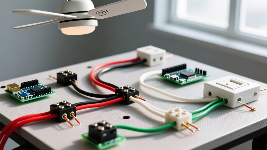

Understanding the Wiring Diagram for Ceiling Fan and Light Setups
Installing a ceiling fan with an integrated light kit is one of the most common residential electrical upgrades. However, interpreting the wiring diagram for ceiling fan and light combinations can be confusing due to the varying configurations of wall switches, house wiring, and manufacturer-specific canopy wires. Whether you are upgrading a standard light fixture to a heavy-duty fan like the Hunter 59244 Dempsey or wiring a new construction dual-switch circuit, understanding the exact wire-to-wire connections is critical for safety and functionality.
This comprehensive guide breaks down the exact wiring diagrams for both single-switch and dual-switch configurations, references the latest National Electrical Code (NEC) requirements for fan-rated boxes, and provides a troubleshooting matrix for common installation failures.
Standard Wire Color Mapping: House vs. Fan
Before making any connections, you must identify the wires in your ceiling junction box and match them to the pigtail wires extending from the fan's motor housing. Most modern ceiling fans (such as those from Minka-Aire, Hunter, and Hampton Bay) follow a standardized color code.
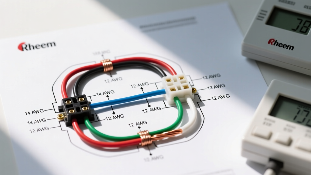
| House Wire (Romex) | Fan Pigtail Wire | Function & Connection Notes |
|---|---|---|
| Bare Copper / Green | Green / Green-Yellow | Equipment Ground. Must be bonded to the metal junction box and fan mounting bracket. |
| White | White (x2) | Neutral. Connect both the fan's white wire and the light kit's white wire to the house neutral. |
| Black | Black | Hot for Fan Motor. Provides power to the fan blades. |
| Red (if 14/3 or 12/3) | Blue | Hot for Light Kit. Provides independent power to the integrated light fixture. |
Pro Tip: Always use a non-contact voltage tester and a multimeter to verify that the circuit is completely de-energized at the breaker panel before touching any bare copper or exposed wire ends. Assume all wires are live until tested.
Scenario A: Single Wall Switch (Pull Chain Control)
In a single-switch configuration, the wall switch controls power to the entire ceiling fan unit. Once the switch is turned on, you must use the pull chains (or a handheld remote receiver) to independently control the fan speed and light brightness. This setup utilizes standard 14/2 or 12/2 NM-B (Romex) cable.
Step-by-Step Wiring Sequence
- Ground Connection: Connect the bare copper house wire to the green ground wire from the fan, the green grounding screw on the mounting bracket, and the metal junction box (if present). Use a green wire nut or a Wago 221 lever nut.
- Neutral Bundle: Twist the white house wire together with both white wires from the fan (one for the motor, one for the light kit). Secure with a yellow wire nut.
- Hot Connection: Connect the black house wire to both the black (fan motor) and blue (light kit) wires from the fan. This ensures the single wall switch sends power to both components simultaneously.
- Secure and Tuck: Carefully fold the wires into the junction box, ensuring no bare copper is exposed outside the wire nuts. Mount the canopy.
Scenario B: Dual Wall Switch (Independent Control)
The dual-switch setup is the most highly requested configuration. It allows you to control the fan motor and the light kit from two separate switches on the wall, eliminating the need for pull chains. This requires a 3-wire cable (14/3 or 12/3 Romex) running from the dual-switch wall box to the ceiling junction box.
The 3-Wire Cable Breakdown
- Black Wire: Carries switched hot power from Switch 1 (typically the fan).
- Red Wire: Carries switched hot power from Switch 2 (typically the light).
- White Wire: Serves as the shared neutral return path.
- Bare Copper: Shared equipment ground.
Step-by-Step Wiring Sequence
- Grounding: Bond all bare copper wires and the green fan wire to the metal box and mounting bracket.
- Neutral: Connect the white house wire to both white wires from the fan.
- Fan Hot: Connect the black house wire exclusively to the black fan wire (motor).
- Light Hot: Connect the red house wire exclusively to the blue fan wire (light kit).
Note: At the wall switch box, the incoming hot (line) wire is pigtailed to the common terminals of both switches. The black load wire goes to Switch 1, and the red load wire goes to Switch 2. The white neutral wire simply passes through the switch box to the ceiling, unless you are installing smart switches that require a neutral connection.
Modern Alternative: Smart Canopy Modules & Fan Speed Controls
If your home is pre-wired with only 14/2 cable (single switch) but you desire independent wall control without tearing open drywall to run 14/3 cable, modern smart home technology offers a code-compliant workaround. Devices like the Lutron Caseta PD-FSQN fan speed control or the Bond RF smart canopy receiver allow independent control of the fan and light via wireless wall switches or smartphone apps.
When installing smart canopy modules, you must ensure the junction box has adequate volume. According to NEC Article 314.16, you must calculate box fill based on the number of conductors and the internal volume of the smart receiver module. Always opt for a deep junction box (minimum 2.5 inches deep) when integrating smart home modules.
NEC Code Requirements: Box Support and Weight Limits
A critical failure point in ceiling fan installations is the junction box itself. Standard light fixture boxes are not rated to handle the dynamic vibration and weight of a ceiling fan. According to CPSC electrical safety guidelines and NEC Article 314.27(D), ceiling fans must be supported by an outlet box specifically listed for fan support.
- Standard Fan-Rated Boxes: Must support a minimum of 35 lbs.
- Heavy-Duty Fan-Rated Boxes: Must support up to 70 lbs (required for large, multi-blade, or cast-iron motor fans).
If you are replacing an existing light fixture with a fan, you must install a fan-rated retrofit brace, such as the Raco 937 Saf-T-Brace. This expandable steel bar wedges between the ceiling joists above the drywall, providing a secure, vibration-free anchor point that meets all 2026 building inspector requirements.
Troubleshooting Matrix: Common Wiring Failures
Even with a correct wiring diagram for ceiling fan and light setups, minor errors can cause operational issues. Use this matrix to diagnose and fix common problems.
| Symptom | Probable Cause | Corrective Action |
|---|---|---|
| Light works, but fan hums and does not spin. | Capacitor failure or incorrect wire pairing (light and motor wires swapped on a dimmer). | Verify the black fan wire is NOT connected to a wall dimmer switch. Dimmers will destroy fan motors. Replace the motor capacitor if wiring is correct. |
| Fan wobbles excessively at high speeds. | Loose mounting bracket or non-fan-rated junction box. | Turn off power. Tighten the mounting bracket screws to the junction box. Install a Raco 937 brace if the box moves. |
| Breaker trips immediately upon turning on the light. | Pinched wire in the canopy or hot/ground short. | Lower the canopy and inspect the blue wire connection. Ensure no bare copper from the hot wire is touching the metal canopy or ground wire. |
| Pull chain works, but wall switch does nothing. | Switch loop wired incorrectly or neutral used as hot. | Use a multimeter to verify the black house wire has 120V when the switch is toggled. Check the switch box for proper line/load orientation. |
Energy Efficiency and Airflow Optimization
Proper wiring is only half the battle; optimizing the fan for energy efficiency is equally important. According to Energy Star specifications, certified ceiling fans are roughly 60% more efficient than standard fan/light units. To maximize airflow and minimize motor strain, ensure the fan is mounted at least 7 feet above the floor and 18 inches away from any walls or sloped ceilings. If installing on a vaulted ceiling, use a downrod extension and a sloped-ceiling adapter ball to ensure the motor housing hangs perfectly plumb, preventing premature bearing wear.
Frequently Asked Questions
Can I use a dimmer switch for both the fan and the light?
No. Standard dimmer switches are designed exclusively for resistive lighting loads. Connecting a ceiling fan motor to a standard dimmer will cause the motor to overheat, hum loudly, and eventually fail. If you want dimmable light and variable fan speed from a single wall plate, you must use a specialized dual-function switch (like the Leviton DW4SF) or a smart fan control module.
What wire gauge should I use for a new ceiling fan circuit?
For a standard 15-amp lighting circuit, 14 AWG copper wire (14/2 or 14/3 Romex) is perfectly adequate and code-compliant. If the circuit is protected by a 20-amp breaker, you must use 12 AWG copper wire (12/2 or 12/3 Romex). Never mix wire gauges on the same circuit.
Do I need to connect the ground wire if my house has older, ungrounded wiring?
If you live in an older home with Knob-and-Tube or early 2-wire Romex lacking a ground, you cannot simply leave the fan's green ground wire floating. NEC code requires you to either run a new grounded circuit from the panel, or install a GFCI breaker/receptacle upstream and label the fan box 'GFCI Protected, No Equipment Ground.' However, for heavy, vibrating appliances like ceiling fans, running a new grounded circuit is the safest and most highly recommended approach.