
Transforming Your Shed into a Vehicle-Centric Power Hub
When DIYers and automotive enthusiasts search for an electrical wiring diagram for a shed, they are usually met with generic guides for basic lighting and a single 15-amp outlet. However, if your shed serves as a vehicle-specific hub—housing an Electric Vehicle (EV) charger, a 50-amp RV hookup, or a DIY auto-repair shop with 240V welders and air compressors—a standard residential branch circuit will fail catastrophically under the load. Designing a robust, code-compliant vehicle hub requires a dedicated subpanel, precise feeder sizing, and an understanding of continuous versus non-continuous loads. This guide provides a comprehensive, vehicle-specific wiring blueprint to ensure your shed can handle the rigorous electrical demands of modern automotive and recreational vehicle equipment.
Why Standard Shed Wiring Fails for Vehicle Applications
Most existing shed circuits are wired with 12 AWG or 14 AWG copper on a 15A or 20A breaker, originating from a main house panel. This setup is adequate for a lawnmower battery trickle charger or a few LED work lights. It is entirely inadequate for vehicle infrastructure for three critical reasons:
- Continuous Load Derating: According to the National Electrical Code (NEC), EV charging is considered a continuous load (operating for 3 hours or more). A 40-amp EV charger requires a circuit rated for 50 amps (125% multiplier). Standard shed wiring will overheat and trip breakers within the first hour of an EV charging session.
- Voltage Drop Over Distance: Sheds are typically 50 to 150 feet from the main service panel. Running a 240V 50A RV air conditioning unit or a Level 2 EV charger over long distances on undersized wire causes severe voltage drop, damaging sensitive vehicle inverters and battery management systems (BMS).
- Harmonic Distortion: Auto shop equipment like Variable Frequency Drives (VFDs) on heavy-duty air compressors introduce harmonic noise back into the circuit, which can interfere with smart EV chargers if they share a neutral bus bar improperly.
The Core Electrical Wiring Diagram for a Shed (Vehicle-Specific)
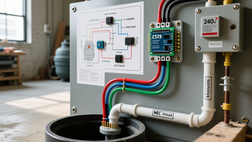
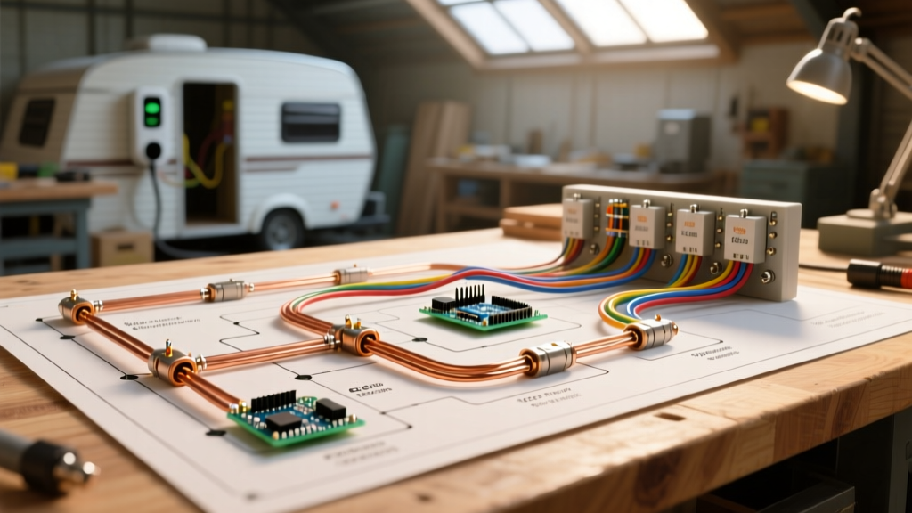
To support a multi-vehicle ecosystem, the optimal electrical wiring diagram for a shed centers around a 100-Amp or 125-Amp Subpanel installed inside the outbuilding. Below is the single-line schematic flow for the installation:
- Main Service Panel (House): Install a 100A 2-pole breaker (e.g., Square D HOM2100).
- Feeder Routing: Run 4-conductor feeder cable (2 Hots, 1 Neutral, 1 Ground) through 1.5-inch Schedule 40 PVC conduit buried at a depth of 24 inches.
- Shed Disconnect (Optional but Recommended): Terminate at an exterior 100A fused disconnect switch before entering the structure.
- Shed Subpanel: Wire into a 12-space, 24-circuit 125A main lug subpanel (e.g., Square D Homeline HOM1224L125PGC).
- Branch Circuits: Distribute power to dedicated vehicle receptacles and hardwired equipment via isolated ground and neutral bus bars.
Circuit Breakdown and Wire Gauge Sizing Matrix
Proper wire sizing is non-negotiable for vehicle safety. The table below details the exact specifications for a comprehensive auto and RV shed setup. All torque specifications must be verified with a calibrated inch-pound torque screwdriver to prevent thermal arcing at the lugs.
| Circuit Application | Breaker Size | Copper THHN (Conduit) | Aluminum XHHW (Conduit) | Termination Torque |
|---|---|---|---|---|
| Main Feeder (100A Subpanel) | 100A 2-Pole | 1 AWG | 1/0 AWG (2-2-2-4 URD) | 120 in-lbs |
| Level 2 EV Charger (48A Cont.) | 60A 2-Pole | 4 AWG | 2 AWG | 45 in-lbs |
| RV 50A Receptacle (NEMA 14-50R) | 50A 2-Pole GFCI | 6 AWG | 4 AWG | 45 in-lbs |
| MIG Welder 240V (e.g., Hobart 210) | 30A 2-Pole | 10 AWG | 8 AWG | 35 in-lbs |
| Air Compressor 240V (5 HP) | 30A 2-Pole | 10 AWG | 8 AWG | 35 in-lbs |
| LED High-Bay Lighting 120V | 15A 1-Pole | 14 AWG | 12 AWG | 15 in-lbs |
Step-by-Step Feeder Installation and Trenching
Executing the underground portion of your electrical wiring diagram for a shed requires adherence to NEC Article 300.5 for underground installations.
1. Trenching and Conduit Selection
Dig a trench exactly 24 inches deep. While direct burial cable (UF-B) is permitted at 24 inches, pulling individual THWN-2 or XHHW conductors through 1.5-inch PVC conduit is vastly superior for future-proofing. Use Schedule 40 PVC underground, but transition to Schedule 80 PVC for the vertical risers where the conduit emerges from the dirt and attaches to the house and shed, as it provides superior impact resistance.
2. Pulling the Feeder
For a 100A feeder, purchase a 2-2-2-4 Aluminum URD (Underground Residential Distribution) cable or pull four individual conductors (two black, one white, one green/bare) using a fiberglass fish tape and wire-pulling lubricant. Aluminum is highly recommended for the feeder run due to cost savings; a 150-foot run of 1/0 Aluminum costs roughly $450, whereas the equivalent Copper SER cable can exceed $1,400.
Grounding, Bonding, and NEC 250.32 Compliance
One of the most frequently failed inspections for outbuildings involves the grounding electrode system. Under NEC 250.32, a separate structure supplied by a feeder must have its own grounding electrode system.
Expert Rule: The neutral and ground bus bars in the shed subpanel MUST be isolated (separated). The only place neutral and ground are bonded is at the main service disconnect. Bonding them in the shed subpanel creates a parallel neutral path, which can energize the shed's metal framing and cause lethal shock hazards.
Install two 5/8-inch by 8-foot copper-clad steel ground rods, driven at least 6 feet apart. Bond them to the subpanel's ground bus bar using a continuous, unspliced run of #6 AWG bare copper wire. Secure the wire with acorn connectors listed for direct burial.
The GFCI Dilemma: RV Receptacles vs. Hardwired EV Chargers
Modern electrical codes have introduced a massive headache for vehicle owners: the GFCI requirement for outdoor and outbuilding receptacles. Understanding how to navigate this is crucial for your shed's vehicle wiring diagram.
The RV 50-Amp Receptacle (NEMA 14-50R)
NEC 210.8(F) mandates that 50A receptacles in outbuildings must have Ground Fault Circuit Interrupter (GFCI) protection. You must install a 50A 2-pole GFCI breaker (e.g., Square D HOM250GFICP, approx. $125). Warning: RVs with internal auto-transfer switches or older inverters often leak milliamps of current to ground, causing nuisance tripping. Ensure your RV's internal grounding scheme is pristine before plugging in.
The EV Charging Workaround
According to the U.S. Department of Energy's EV charging guidelines, Level 2 chargers should ideally be hardwired. If you install a NEMA 14-50R receptacle for your EV charger, the NEC requires a GFCI breaker. However, EV chargers (like the Tesla Wall Connector or ChargePoint Home Flex) already have internal GFCI protection. Stacking a GFCI breaker on top of a GFCI EVSE causes constant, frustrating trip faults. The solution: Hardwire your EV charger directly to a standard 60A breaker. Hardwired EVSEs are exempt from the receptacle GFCI rule because the internal GFCI satisfies the safety requirement.
Edge Cases: Voltage Drop and Harmonic Distortion
If your shed is located more than 100 feet from the main panel, voltage drop becomes a critical factor. The NEC recommends a maximum 3% voltage drop for branch circuits and 5% total for feeder plus branch. If you are running a 50A RV AC unit and a 48A EV charger simultaneously, the voltage sag on 2 AWG aluminum might cause the RV's compressor to stall and overheat. In runs exceeding 120 feet, upsize your feeder to 1/0 AWG or even 2/0 AWG Aluminum to maintain a robust 240V at the subpanel lugs under heavy load.
Furthermore, if your auto shop includes a plasma cutter or a VFD-driven rotary screw compressor, these devices generate severe harmonic distortion. To prevent this noise from corrupting the data signals in your smart EV charger, wire the EV charger and the heavy inductive loads on opposite phases (legs) of the 240V subpanel, and ensure your subpanel neutral is sized identically to the hot conductors to handle any triplen harmonics that may accumulate.
Final Inspection and Energization
Before energizing the subpanel, use a digital multimeter to verify continuity between the ground bus and the grounding rods, and ensure infinite resistance (no continuity) between the neutral bus and the ground bus. Torque all lugs to manufacturer specifications. Once the local Authority Having Jurisdiction (AHJ) signs off on the trenching, conduit, and panel terminations, your vehicle-specific shed hub will be ready to safely power your fleet for decades to come.