
The Hidden Safety Risks in Electrical Schematics
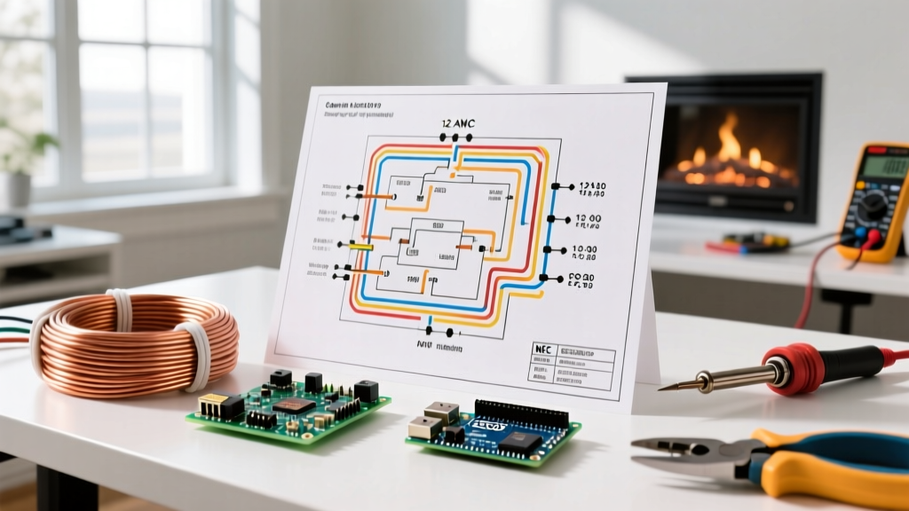
When electricians and engineers evaluate symbols for wiring diagrams, the focus is often on circuit functionality. However, from a safety and code compliance perspective, misinterpreting a single schematic symbol can lead to catastrophic arc flash events, failed municipal inspections, and severe National Electrical Code (NEC) violations. As jurisdictions across the US accelerate their adoption of the 2023 and upcoming 2026 NEC cycles, the demand for strict adherence to standardized drafting symbols has never been higher.
A wiring diagram is a legal and technical document. If a contractor installs a 3-pole breaker where a diagram implies a 4-pole (bringing a neutral into a 3-phase motor circuit), the resulting ground fault could destroy thousands of dollars in equipment. This guide breaks down the critical safety symbols you must know to ensure your electrical installations pass inspection and protect human life.
The ANSI vs. IEC Divide: Why Standardization Matters
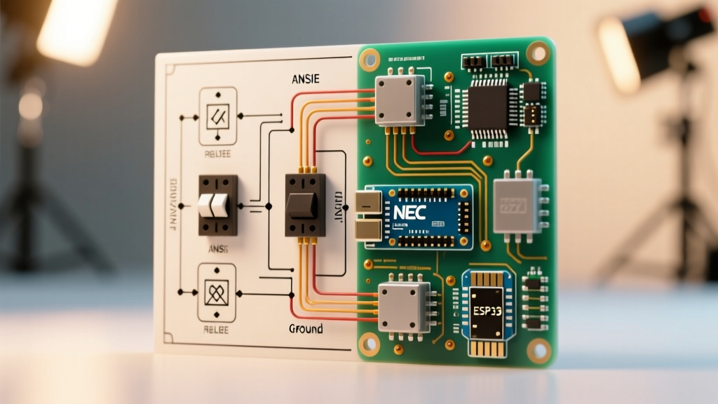
The most common compliance trap for US-based electrical professionals is mixing International Electrotechnical Commission (IEC 60617) symbols with American National Standards Institute (ANSI/IEEE 315) symbols. US electrical inspectors base their approvals on the NFPA 70 (NEC), which inherently relies on ANSI/IEEE conventions for panel schedules and schematics.
| Component | ANSI/IEEE 315 (US Standard) | IEC 60617 (International) | Compliance Risk if Mixed |
|---|---|---|---|
| Resistor | Zigzag line | Empty rectangle | Misidentified as a relay coil or heater element. |
| Ground | Three descending horizontal lines | Single line with three downward branches | Confusion between earth ground and chassis ground. |
| Relay Coil | Circle or semicircle with 'M' or 'CR' | Rectangle with diagonal lines | Technician fails to isolate control voltage during LOTO. |
| Circuit Breaker | Square with a manual/thermal trip curve | Rectangle with an 'x' or cross | Incorrect fault-current rating assumptions. |
Grounding and Bonding Symbols: NEC Article 250
Grounding is the backbone of electrical safety. Misreading grounding symbols directly violates NEC Article 250, which governs grounding and bonding. In commercial and industrial settings, distinguishing between an Equipment Grounding Conductor (EGC) and a Grounding Electrode Conductor (GEC) is vital.
The Isolated Ground (IG) Symbol
In healthcare facilities (governed by NEC Article 517) and sensitive data centers, you will frequently encounter the Isolated Ground symbol: a standard ground symbol enclosed within a triangle.
- The Code Requirement: An IG receptacle requires a dedicated, insulated equipment grounding conductor that bypasses all intermediate panelboards and connects directly to the applicable derived source or service equipment.
- The Cost of Error: If an electrician misreads the IG symbol as a standard ground and bonds it to a local subpanel, they create a ground loop. In a hospital setting, this can introduce micro-shock hazards to patients. Reworking a commercial IG circuit typically costs $250 to $400 per drop in labor and materials to pull a new dedicated green wire back to the main switchgear.
Overcurrent Protection and AFCI/GFCI Notations
Modern electrical diagrams must explicitly denote the type of overcurrent protection to satisfy NEC Articles 210, 240, and 409. A generic breaker symbol is no longer sufficient for residential or light commercial plans.
Code Warning: If a schematic shows a standard thermal-magnetic breaker symbol on a 15A or 20A, 120V branch circuit feeding a bedroom or living area, the plan will be rejected by the AHJ (Authority Having Jurisdiction). The symbol must explicitly indicate an AFCI (Arc-Fault Circuit Interrupter) or a dual-function AFCI/GFCI breaker.
Identifying Specific Breaker Symbols
Advanced schematics for Motor Control Centers (MCCs) and industrial panels use specific notations for electronic trip units versus thermal-magnetic trips. For example, a breaker frame like the Eaton G-Frame or Siemens VL might feature a symbol indicating an LSI (Long-time, Short-time, Instantaneous) trip unit.
If the diagram uses a standard instantaneous-only (magnetic) breaker symbol for a main feeder, but the engineer intended an LSI trip for selective coordination (NEC 580), a downstream fault could trip the main 2000A service instead of the 400A feeder, blacking out an entire facility.
Control Circuit Safety: NO vs. NC Contacts
When reviewing control schematics for industrial machinery, adherence to OSHA electrical safety standards and NFPA 79 is mandatory. The distinction between Normally Open (NO) and Normally Closed (NC) contacts is a matter of life and death, particularly regarding Emergency Stop (E-Stop) circuits.
- Normally Open (NO): Represented by two parallel lines with a gap. Used for start buttons and permissive interlocks. Power must be applied to close the circuit.
- Normally Closed (NC): Represented by two parallel lines crossed by a diagonal line. Used for stop buttons and E-Stops.
- The Fail-Safe Rule: E-Stop circuits must be wired using NC contacts in a series loop. If a wire breaks or a connection vibrates loose, the circuit opens, and the machine stops safely. If a technician misreads the symbol and wires an E-Stop using NO contacts, a broken wire will render the E-Stop completely useless—a massive liability and an immediate OSHA citation during an audit.
Wire Routing, Conduit Fill, and Phase Notations
Wiring diagrams often include routing annotations that impact NEC Chapter 9, Table 1 (conduit fill capacities). A common shorthand is the use of slash marks across a single drawn line to indicate multiple conductors (e.g., three slashes for a 3-wire circuit).
Decoding Wire Callouts
Proper interpretation of wire callouts prevents overheating and voltage drop violations. Consider the annotation: 3/C #10 THHN + #10 GRN
- 3/C #10 THHN: Three current-carrying conductors, 10 AWG, with THHN insulation (rated 90°C in dry locations, but ampacity must be calculated at the 60°C or 75°C column per NEC 110.14(C)).
- + #10 GRN: An insulated equipment grounding conductor. While a bare copper ground is standard in many commercial builds, an insulated green wire is required in specific environments, such as hazardous locations or certain healthcare applications.
- Conduit Fill Impact: The EGC counts toward the physical conduit fill area (Chapter 9), even though it does not count as a current-carrying conductor for derating purposes (NEC 310.15(C)(1)). Misreading the callout and assuming the ground is bare (and thus ignoring its cross-sectional area) can result in an overfilled conduit, leading to heat buildup and insulation failure.
Real-World Failure Case Study: The Fire Alarm Relay
In a recent 2025 commercial retrofit, an HVAC contractor was tasked with integrating rooftop units (RTUs) with a new fire alarm control panel (FACP). The schematic provided by the FACP manufacturer showed a relay contact symbol for the "Fan Shutdown" circuit. The contractor interpreted the symbol as a Normally Open (NO) contact that would close to energize a shunt-trip breaker upon an alarm.
However, the symbol actually represented a Normally Closed (NC) contact designed to drop power from a continuous-duty relay coil (a fail-safe design required by ANSI/IEEE 315 and NFPA 72). When the fire alarm triggered, the relay opened, but because the HVAC shunt-trip was wired expecting a closed circuit to provide the trip voltage, the RTU fans continued running, pumping smoke through the building. The subsequent forensic investigation cost the contractor over $15,000 in legal and rework fees, highlighting why symbol literacy is a core safety competency.
Frequently Asked Questions (FAQ)
Are hand-drawn wiring diagrams legally acceptable for permits?
While some rural jurisdictions may accept clean, hand-drawn schematics for simple residential additions, most commercial and industrial AHJs require CAD-generated diagrams using standardized ANSI/IEEE 315 symbol libraries to ensure clarity and code compliance during the plan review process.
What does a circle with a diagonal cross mean on a panel schedule?
In ANSI/IEEE schematics, a circle with a cross often denotes a specific type of current transformer (CT) or a specialized metering sensor. However, in IEC diagrams, a rectangle with an 'X' denotes a circuit breaker. Always verify the title block's standard reference before proceeding.
How do I denote a multi-wire branch circuit (MWBC) on a diagram?
An MWBC must be clearly identified, often by grouping the phase conductors with a bracket or a specific label (e.g., "Phase A & B, Handle-Tied"). Per NEC 210.4, the diagram must visually indicate that the ungrounded conductors are fed from different phases and share a single neutral, requiring a common-trip or handle-tied breaker symbol.