
Decoding the Electrical Wiring Diagram of House Panels
When homeowners and DIYers search for an electrical wiring diagram of house circuits, they are often met with oversimplified schematics showing basic light switches and receptacles. However, the true nerve center of any residential electrical system is the main service panel. Understanding how to read, interpret, and draft a panel-specific wiring diagram—often referred to as a panel schedule or single-line diagram—is critical for safe upgrades, troubleshooting, and ensuring compliance with modern electrical codes. In 2026, with the proliferation of Level 2 EV chargers, smart home subpanels, and solar battery integrations, the complexity of residential panels has increased dramatically.
This guide bridges the gap between basic residential schematics and professional panel schedules, giving you the exact breaker sizing, wire gauge matrices, and troubleshooting frameworks needed to master your home's electrical distribution.
Anatomy of a Residential Service Panel Diagram
A professional electrical diagram for a house panel does not look like a traditional circuit schematic with zig-zag resistors and battery symbols. Instead, it relies on a single-line diagram format and a panel schedule. Here are the core components you must identify on any panel diagram:
- Main Service Disconnect: Usually a 200-Amp or 400-Amp double-pole breaker at the top of the diagram. In modern 2026 installations, 400A service is becoming standard for all-electric homes to support heat pumps and EV charging simultaneously.
- Hot Bus Bars (Phases A and B): Represented by two parallel vertical lines. In a standard North American split-phase system, each leg provides 120V relative to neutral, and 240V phase-to-phase.
- Neutral and Ground Bus Bars: Often depicted as a single bar in the main service panel (where neutral and ground are bonded), but shown as strictly separated bars in any subpanel diagrams.
- Branch Circuit Routing: Lines branching off the hot bus bars, passing through breaker symbols (single or double-pole), and routing to specific loads.
Safety Warning: Never rely solely on the paper panel schedule taped to the inside of your breaker box door. Previous homeowners or unlicensed handymen frequently move breakers without updating the diagram. Always verify the physical wiring with a non-contact voltage tester and a multimeter before touching any bus bars or terminals.
Breaker Sizing and Wire Gauge Matrix (2026 Standards)
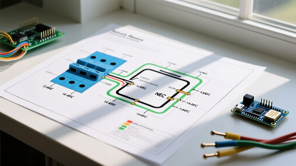
A critical component of any house electrical wiring diagram is the correlation between the breaker amperage and the wire gauge. The National Electrical Code (NEC) strictly dictates these pairings to prevent thermal runaway and fires. Below is a reference matrix based on standard 60°C/75°C copper (NM-B and THHN) column ratings.
| Breaker Size (Amps) | Pole Configuration | Min. Copper Wire (AWG) | Typical 2026 Application | Est. Material Cost |
|---|---|---|---|---|
| 15A | Single-Pole | 14 AWG | General lighting, older receptacles | $0.15 / ft |
| 20A | Single-Pole | 12 AWG | Kitchen/bath receptacles, garage tools | $0.22 / ft |
| 30A | Double-Pole | 10 AWG | Standard electric dryers, water heaters | $0.45 / ft |
| 40A | Double-Pole | 8 AWG | Electric ranges, older HVAC condensing units | $0.85 / ft |
| 50A | Double-Pole | 6 AWG | Level 2 EV Chargers (e.g., ChargePoint Home Flex) | $1.40 / ft |
| 60A | Double-Pole (Subpanel Feed) | 4 AWG (or 6 AWG THHN in conduit) | Detached garage subpanels, workshop feeds | $2.10 / ft |
Note: When drafting your diagram, always specify the wire insulation type (e.g., NM-B Romex vs. individual THHN in conduit), as this drastically alters the allowable ampacity under NEC Article 310.
Decoding Panel Schedules vs. Schematics
It is vital to understand the difference between the two primary types of diagrams used in residential wiring:
1. The Panel Schedule (The Physical Map)
This is the grid printed on your panel door. It lists the circuit number, description, and breaker amperage. Odd numbers (1, 3, 5) are on the left bus bar (Phase A), and even numbers (2, 4, 6) are on the right bus bar (Phase B). When designing a panel layout, electricians use the schedule to balance the load across both phases. If Phase A carries 80 Amps of continuous load and Phase B carries only 20 Amps, the main neutral wire will carry the 60-Amp difference, potentially causing voltage drop and overheating.
2. The Single-Line Schematic (The Logical Map)
Used for complex upgrades like adding a solar inverter or a backup generator transfer switch, this diagram abstracts the physical panel. It shows the flow of power from the utility drop, through the meter, into the main disconnect, and out to subpanels. According to the U.S. Department of Energy, understanding this logical flow is essential for integrating renewable energy systems and battery backups safely without backfeeding the grid.
Modern NEC Compliance in House Wiring Diagrams
If you are updating an electrical wiring diagram of house circuits for a remodel or new addition, your diagram must reflect current National Electrical Code (NEC) requirements. The days of standard thermal-magnetic breakers for every circuit are over.
- AFCI Protection (NEC 210.12): Almost all 120V, 15A and 20A branch circuits supplying living rooms, bedrooms, kitchens, and hallways require Arc-Fault Circuit Interrupter protection. On your diagram, denote these with the label "AFCI" or specify Dual Function (CAFI/GFI) breakers, such as the Square D QO 20-Amp Dual Function breaker (retailing around $48-$55 in 2026).
- GFCI Protection (NEC 210.8): Required for bathrooms, garages, outdoors, crawl spaces, and within 6 feet of a sink. Your diagram should clearly mark these circuits as "GFCI Protected" either at the breaker or via a downstream GFCI receptacle.
- Dedicated Circuits: Modern diagrams must explicitly show dedicated, unshared circuits for high-draw appliances. A refrigerator, microwave, and dishwasher should each have their own dedicated 20A circuit, clearly labeled on the schematic to prevent future DIYers from tapping into them for general lighting.
Step-by-Step: Tracing a 240V EV Charger Circuit on a Diagram
Let us walk through how a professional electrician diagrams a 50-Amp Level 2 EV charger installation, from the main panel to the NEMA 14-50 receptacle.
- Panel Origin: The diagram starts at the 200A Main Service Panel. A 50A double-pole breaker (e.g., Eaton BR 250, approx. $32) is assigned to slots 4 and 6, ensuring it pulls 240V across both Phase A and Phase B.
- Wire Routing: The schematic specifies 6 AWG Copper THHN/THWN-2 (4 wires: Black, Red, White, Green) routed through 3/4-inch EMT metallic conduit. NM-B (Romex) is generally avoided in exposed garage runs due to physical damage vulnerabilities.
- Disconnect Switch: For hardwired units over 60A, or per local inspector preference, a 60A non-fused AC disconnect switch is drawn inline, mounted within sight of the charger.
- Termination Point: The line terminates at a NEMA 14-50R receptacle. The diagram must explicitly note that the neutral (white) is connected to the silver terminal, and the ground (green/bare) is connected to the U-shaped ground pin. Never bond neutral and ground at a receptacle.
When the Diagram Lies: Troubleshooting Field Discrepancies
The most dangerous aspect of residential electrical work is assuming the existing electrical wiring diagram of house panels is accurate. When auditing an older home, look for these common, hazardous discrepancies that are rarely documented on paper:
Multi-Wire Branch Circuits (MWBCs) Without Handle Ties
An MWBC uses a single 3-wire cable (Black, Red, White/Neutral) to feed two separate 120V circuits on opposite phases, sharing one neutral wire. If a previous owner replaced the original double-pole breaker with two separate single-pole breakers and placed them on the same phase, the shared neutral will carry the combined amperage of both circuits, leading to a melted neutral bus bar or fire. Modern code requires a factory-installed handle tie or a single double-pole breaker. Always verify MWBCs with a clamp meter on the neutral wire while both circuits are under load.
Double-Tapped Breakers
Unless the breaker is explicitly designed and labeled for two conductors (like many Square D QO and Homeline single-pole breakers), clamping two wires under a single terminal screw is a severe fire hazard and an NEC violation. If your physical panel shows double-tapping but the diagram shows a single circuit, you must redraw the diagram and install a pigtail or a tandem breaker to correct the physical fault.
Subpanel Bonding Errors
A diagram might show a subpanel in a detached shed, but fail to indicate that the neutral and ground bus bars must be isolated from one another in the subpanel, and bonded only at the main service disconnect. Furthermore, a detached structure requires a separate grounding electrode system (like two 8-foot copper ground rods). If your schematic omits the ground rods, the installation is incomplete and dangerous.
Conclusion
Mastering the electrical wiring diagram of house panels is not just about passing an inspection; it is about creating a living document that ensures the safety and scalability of your home's power infrastructure. Whether you are balancing loads on a Square D QO 200-Amp main panel, upgrading to AFCI breakers, or wiring a heavy-duty 240V EV circuit, precise diagramming, strict adherence to wire gauge matrices, and rigorous field verification are your best defenses against electrical hazards. Always consult a licensed master electrician and your local Authority Having Jurisdiction (AHJ) before executing high-amperage panel modifications.