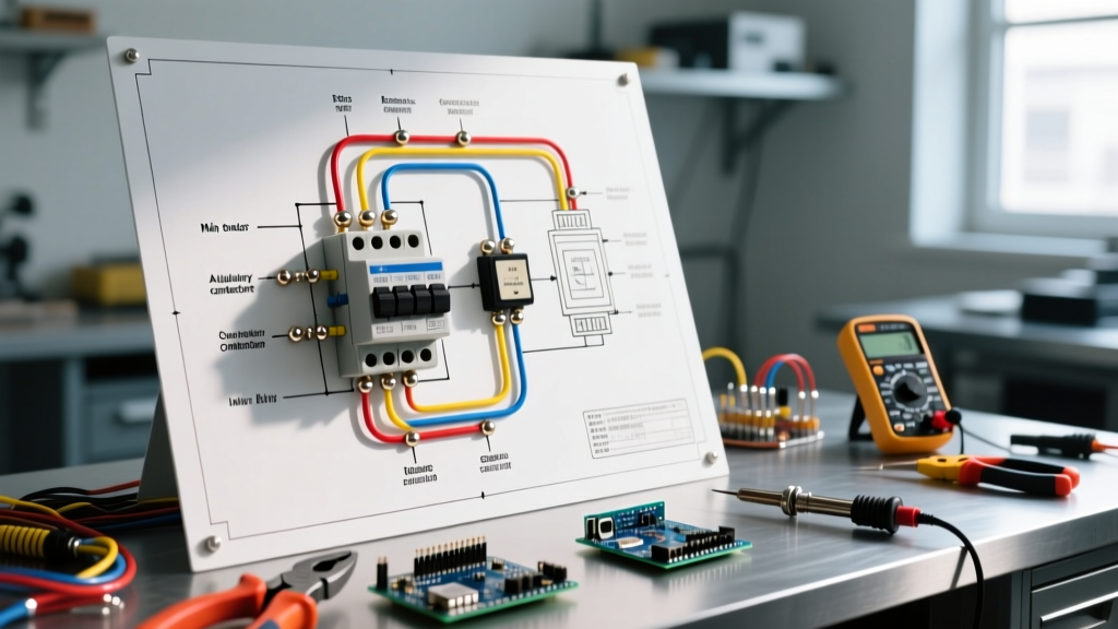

Strategic Planning for Star-Delta Motor Starter Installations
Designing and installing a reduced-voltage starter requires meticulous attention to detail. When reviewing a wiring diagram for star delta motor starter configurations, the primary engineering objective is to limit the starting current surge to approximately 33% of the Direct-On-Line (DOL) equivalent, thereby mitigating severe voltage dips on the facility’s main bus. This method is the industry standard for 3-phase squirrel cage induction motors ranging from 5 HP (4 kW) up to 500 HP (375 kW) where high starting torque is not strictly required.
However, interpreting the schematic is only the first step. A successful installation in 2026 demands precise component sizing, rigorous phase-sequence verification, and strategic overload relay placement. According to the NFPA 70 (National Electrical Code) Article 430, motor circuit conductors and protection devices must be sized based on the motor’s Full Load Current (FLC), but the star-delta topology introduces unique current distribution paths that alter standard sizing rules.
Component Sizing Matrix: The 58% and 33% Rules
The most common mistake journeyman electricians make when executing a star-delta wiring diagram is sizing all three contactors equally. Because the motor windings are reconfigured, the current flowing through each contactor varies drastically depending on its position in the circuit.
- Main Contactor (KM1): Carries the line current during both Star and Delta modes. During Delta (run) mode, the winding current is 58% (1/√3) of the motor’s rated FLC.
- Delta Contactor (KM2): Closes the delta loop. It only carries current during the run phase, also rated at 58% of the motor FLC.
- Star Contactor (KM3): Short-circuits the winding tails during the start phase. Because the voltage applied to each winding is reduced to 58%, the current drawn is reduced to 33% of the DOL starting current, which translates to roughly 33% of the motor’s rated FLC.
Sizing Example: 50 HP (37 kW), 460V, 3-Phase Motor
For a standard 50 HP motor with a nameplate FLC of 65 Amps, we apply the star-delta multipliers to select appropriate 2026-market contactors, such as the Schneider Electric TeSys Giga or ABB AF series.
| Component | Sizing Multiplier | Calculated Current | Recommended Frame Size | 2026 Est. Unit Cost |
|---|---|---|---|---|
| Main Contactor (KM1) | 58% of FLC | 37.7 A | 40A - 50A (e.g., LC1D50) | $185 - $220 |
| Delta Contactor (KM2) | 58% of FLC | 37.7 A | 40A - 50A (e.g., LC1D50) | $185 - $220 |
| Star Contactor (KM3) | 33% of FLC | 21.4 A | 25A - 32A (e.g., LC1D32) | $110 - $140 |
| Thermal Overload Relay | See Placement Rules | Variable | LRD3357 (37-50A range) | $165 - $190 |
Power Circuit Topology and Phase Sequencing
When mapping the power circuit from the wiring diagram, terminal designations are non-negotiable. The supply lines (L1, L2, L3) must connect to the motor terminals U1, V1, and W1 via the Main Contactor (KM1). The Star Contactor (KM3) bridges U2, V2, and W2 together to form the neutral star point.
Critical Warning: Phase Sequence Reversal
The most catastrophic failure mode in a star-delta installation is incorrect cross-wiring of the Delta Contactor (KM2). When transitioning to Delta, U2 must connect to the L2 phase, V2 to L3, and W2 to L1. If you mistakenly wire U2 to L1, the motor will instantly reverse its direction of rotation upon transition. This causes a massive mechanical shock that can shear the motor shaft and a current spike that will weld the contactors shut.
To prevent this, always use a phase rotation meter (such as the Fluke 87V with a phase attachment or a dedicated Fluke 9040) to verify the sequence at the motor peckerhead before finalizing the delta loop connections. Referencing the NEMA MG-1 Motors and Generators standard ensures your terminal markings align with standard North American 3-phase conventions.
Thermal Overload Relay (OLR) Placement Strategies
The wiring diagram for a star delta motor starter offers two distinct locations for the Thermal Overload Relay, which fundamentally changes how you set the trip dial:
- Line-Side Placement (Before KM1): The OLR measures the total line current. In this configuration, set the OLR dial to 100% of the motor’s nameplate FLC (e.g., 65A). This is the easiest to wire but requires a larger, more expensive OLR frame.
- Delta-Loop Placement (Between KM1/KM2 and the Motor): The OLR is placed in the circuit branches that only carry the winding current during the Delta run phase. Because the winding current is 58% of the line current, you must set the OLR dial to 58% of the motor FLC (e.g., 37.7A). This allows you to use a smaller, more cost-effective OLR and provides highly accurate protection during the run state.
Control Circuit Logic: Interlocks and Transition Timers
A robust control circuit relies on both electrical and mechanical interlocks. Relying solely on electrical interlocks (wiring the Normally Closed [NC] auxiliary contacts of KM2 into the KM3 coil circuit, and vice versa) is insufficient. If a contactor welds shut due to an arc flash, the electrical interlock will fail to prevent the opposing contactor from pulling in, resulting in a dead-phase-to-phase short circuit.
Installation Requirement: Always install a physical mechanical interlock block (e.g., Schneider LAD9R1V or ABB VB1325) between the Delta and Star contactors. This physically prevents the armatures from closing simultaneously, regardless of coil voltage.
Calculating the Star-to-Delta Transition Timer
The transition timer dictates how long the motor runs in Star before switching to Delta. If the timer is too short, the motor hasn’t reached sufficient speed, and the Delta transition will cause a current spike nearly equal to a DOL start. If it’s too long, the Star contactor will overheat, as it is only rated for 33% FLC and lacks the thermal mass for prolonged starting.
While a common rule of thumb formula is t = 2√P + 4 (where P is motor power in kW), the U.S. Department of Energy’s Advanced Manufacturing Office recommends empirical tuning for high-inertia loads. Clamp an ammeter around L1, start the motor in Star, and observe the current decay. Set the timer to transition exactly when the current needle stops dropping and stabilizes (typically between 6 and 15 seconds for standard centrifugal pumps and fans).
Edge Cases and Troubleshooting Matrix
Even with a perfect wiring diagram for star delta motor starter layouts, field conditions introduce variables. Use this troubleshooting matrix during commissioning:
- Motor trips on OLR during Star phase: The load inertia is too high for a star-delta starter (starting torque is only 33% of DOL). The motor stalls. Solution: Upgrade to an Auto-Transformer starter or a Variable Frequency Drive (VFD).
- Star contactor contacts are pitted/welded: The transition timer is set too long, causing the under-sized Star contactor to carry starting current past its thermal limit. Solution: Reduce timer setting or upgrade KM3 to the same frame size as KM1/KM2.
- Massive vibration upon Delta transition: Phase sequence error in the Delta loop. Solution: Swap two of the delta cross-connections at the motor peckerhead immediately.
Frequently Asked Questions
Can I use a star-delta starter for a single-phase motor?
No. Star-delta starting strictly requires a 3-phase motor with all six winding leads (U1, V1, W1, U2, V2, W2) brought out to the terminal box. Single-phase motors utilize different starting mechanisms, such as capacitor-start or split-phase designs.
Is a star-delta starter considered an open or closed transition?
Standard star-delta wiring diagrams utilize an open transition. This means the motor is completely disconnected from the power supply for a brief fraction of a second (usually 50-100 milliseconds) between the Star contactor opening and the Delta contactor closing. For applications where power interruption causes unacceptable torque pulsations, a closed-transition star-delta starter (which uses transition resistors) is required, though it is significantly more complex and expensive to wire.