
The Critical Role of Wire Gauge and Color Coding in Electric Heating
Electric heating systems are among the most demanding continuous loads in any residential or commercial electrical panel. Whether you are installing a simple 1500W Cadet baseboard heater or a massive 15kW Goodman central air handler heat strip, misinterpreting an electric heat wiring diagram can lead to catastrophic results. Undersized wires melt, breakers trip incessantly, and improper color coding creates lethal shock hazards for future technicians.
This comprehensive guide bridges the gap between the schematic on your equipment's wiring diagram and the physical copper (or aluminum) conductors you pull through the walls. We will break down the National Electrical Code (NEC) requirements for continuous loads, map out exact wire gauge selections based on 2026 market-standard equipment, and clarify the color code rules that keep your installation legal and safe.
Decoding the Electric Heat Wiring Diagram: Core Components
Before cutting any wire, you must understand what the manufacturer's schematic is actually telling you. Every standard electric heat wiring diagram will feature three primary circuit segments:
- The Branch Circuit (Line Side): The conductors running from your main or sub-panel breaker to the heater's junction box or contactor.
- The Control Circuit (Thermostat/Relay): Often low-voltage (24V) for central systems, or line-voltage (120V/240V) for baseboard units. These wires trigger the heavy-duty contactors.
- The Load Side: The internal wiring connecting the contactor to the actual resistive heating elements (usually Nichrome wire coils).
When sizing your wire and selecting your color codes, your primary focus is the Branch Circuit. The wiring diagram will specify the Minimum Circuit Ampacity (MCA) and the Maximum Overcurrent Protection (breaker size). You must use the MCA, not the breaker size, to determine your wire gauge.
Wire Gauge Sizing: The 125% Continuous Load Rule
According to NFPA 70 (National Electrical Code) Article 210.19(A)(1) and Article 424, fixed electric heating equipment is classified as a continuous load because it is expected to run for three hours or more. Therefore, the branch circuit conductors must be sized at 125% of the total amperage draw.
Below is a practical reference table for standard 240V electric heating applications, reflecting standard copper (CU) THHN/THWN-2 and NM-B (Romex) ampacities at 60°C/75°C termination ratings.
| Heater Wattage (240V) | Base Amperage | 125% Continuous Load | Min Wire Gauge (Copper) | Standard Breaker Size |
|---|---|---|---|---|
| 1,500W (e.g., Cadet F1504) | 6.25A | 7.8A | 14 AWG (12 AWG Rec.) | 15A (2-Pole) |
| 2,000W | 8.33A | 10.4A | 14 AWG (12 AWG Rec.) | 15A (2-Pole) |
| 3,000W | 12.5A | 15.6A | 12 AWG | 20A (2-Pole) |
| 4,000W | 16.6A | 20.8A | 10 AWG | 25A or 30A (2-Pole) |
| 5,000W (e.g., Garage Heater) | 20.8A | 26.0A | 10 AWG | 30A (2-Pole) |
| 10,000W (e.g., Goodman HKR10) | 41.6A | 52.0A | 6 AWG | 60A (2-Pole) |
2026 Pricing Note: When budgeting for your installation, a 250-foot spool of 10/2 NM-B copper cable averages around $290 to $320, while 6/2 NM-B has climbed to approximately $580 to $640 per spool. For long runs in conduit, individual 6 AWG THHN wire is significantly more cost-effective at roughly $1.45 per foot.
NEC Color Code Standards for Heating Circuits
Color coding is where many DIYers and novice electricians make dangerous mistakes when following an electric heat wiring diagram. The NEC mandates strict color assignments to prevent cross-wiring and ensure safety during maintenance.
Scenario A: 240V Baseboard Heater (No Neutral Required)
Most simple resistive baseboard heaters and wall heaters require only two hot legs and a ground. They do not use a neutral wire because there are no 120V control boards or motors.
- Hot Leg 1: Black
- Hot Leg 2: Red (or Black with red tape)
- Ground: Bare Copper or Green
CRITICAL NEC WARNING: If you are using standard 12/2 or 10/2 NM-B cable (which contains one Black, one White, and one Bare wire) to feed a 240V-only heater, you are using the White wire as a hot leg. Per NEC Article 200.7(C), you must permanently re-identify the white wire with black or red electrical tape, or heat-shrink tubing, at both the panel and the heater junction box. Failure to do so is a severe code violation and a shock hazard.
Scenario B: 240V/120V Electric Furnace or Air Handler (Neutral Required)
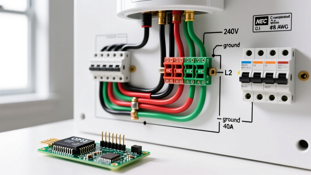
Central electric furnaces and air handlers require a neutral wire to power the 120V blower motor, control boards, and relays, while using 240V for the heavy heat strips. You must use a 4-wire cable (e.g., 8/3 or 6/3 NM-B) or pull four individual wires in conduit.
- Hot Leg 1 (240V): Black
- Hot Leg 2 (240V): Red
- Neutral (120V Return): White (Must remain white; never re-identify)
- Equipment Ground: Bare Copper or Green
For deeper insights into conductor insulation types and temperature ratings, the Copper Development Association (CDA) provides excellent reference matrices for matching THHN, XHHW, and NM-B jackets to specific ambient temperatures in attics and crawlspaces.
Real-World Edge Cases: Voltage Drop and Distance
An electric heat wiring diagram assumes ideal conditions. It does not account for a 150-foot wire run to a detached workshop. When wire runs exceed 100 feet, voltage drop becomes a major factor. Resistive heaters are highly sensitive to voltage drop; a 10% drop in voltage results in a 19% drop in heating output (Wattage = Volts² / Resistance).
The Fix: If you are installing a 5,000W (20.8A) heater in a detached garage 150 feet from the panel, standard 10 AWG wire will yield a voltage drop of roughly 4.8%. While the NEC recommends a maximum 3% drop for branch circuits, you should upgrade to 8 AWG copper to bring the drop down to an acceptable 3.0%, ensuring your heater actually produces its rated BTU output.
Common Wiring Failure Modes & Troubleshooting
Even if you follow the diagram perfectly, physical installation errors can cause system failures. Here are the most common edge cases we see in the field:
- Thermal Expansion Loosening: Electric heaters cycle on and off, causing terminal blocks to heat up and cool down. This thermal expansion and contraction will loosen wire connections over time. Solution: Always use a calibrated torque screwdriver. Most Cadet and Marley baseboard terminals require 12 to 15 in-lbs of torque. Apply an anti-oxidant compound (like Noalox) if using aluminum wire.
- Miswired Line-Voltage Thermostats: Line-voltage thermostats often have a 'Line' and 'Load' side. If you wire the panel feed into the 'Load' side, the thermostat's internal heat anticipator (if equipped) or electronic sensor will malfunction, causing severe temperature overshooting.
- Shared Neutral Overloads: In older multi-wire branch circuits (MWBC), two 120V heater circuits might share a single neutral. If both heaters are on the same phase (due to a breaker installation error), the neutral wire will carry the sum of both currents, overheating the white wire while the breaker remains untripped. Always ensure MWBC breakers are on opposite phases and feature a handle tie.
Frequently Asked Questions (FAQ)
Can I use aluminum wire for electric heat strips?
Yes, but only for larger central systems (typically 40A and above) and only if the equipment's wiring diagram and terminal lugs are explicitly rated for aluminum (marked AL or CU-AL). For a 10kW heat strip requiring 6 AWG Copper, you would need to upgrade to 4 AWG AA-8000 series Aluminum. Never use aluminum for small 14 AWG or 12 AWG baseboard heater branch circuits.
Why does my wiring diagram show a 2-pole breaker but the thermostat only breaks one leg?
Some older or budget line-voltage thermostats are single-pole, meaning they only interrupt one of the two 120V hot legs. While this turns the heater off, the internal elements remain energized at 120V to ground. The NEC allows this, but for safety, it is highly recommended to upgrade to a double-pole line-voltage thermostat that breaks both hot legs simultaneously, ensuring zero voltage reaches the elements when off.
Do I need a GFCI or AFCI breaker for electric baseboard heat?
Generally, no. Standard thermal-magnetic breakers are used. However, if the electric heat wiring diagram specifies an installation in a bathroom or an area requiring AFCI protection under your local 2026 adopted building codes, you must use the appropriate listed breaker. Note that the high inrush current of some heating elements can cause nuisance tripping on older AFCI breakers; always use the manufacturer-recommended breaker model.
Final Safety Reminders
Working with 240V circuits leaves zero margin for error. Always verify power is off using a CAT III or CAT IV non-contact voltage tester and a digital multimeter before touching any terminals. For comprehensive safety protocols regarding lockout/tagout and live-circuit testing, refer to the OSHA Electrical Safety Guidelines. When in doubt, consult a licensed master electrician to review your specific electric heat wiring diagram and load calculations.