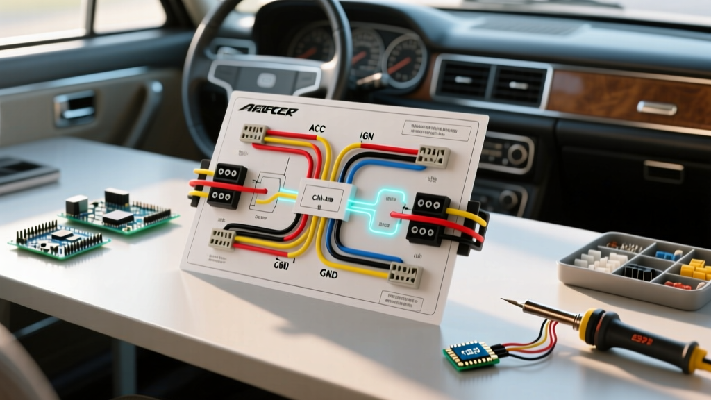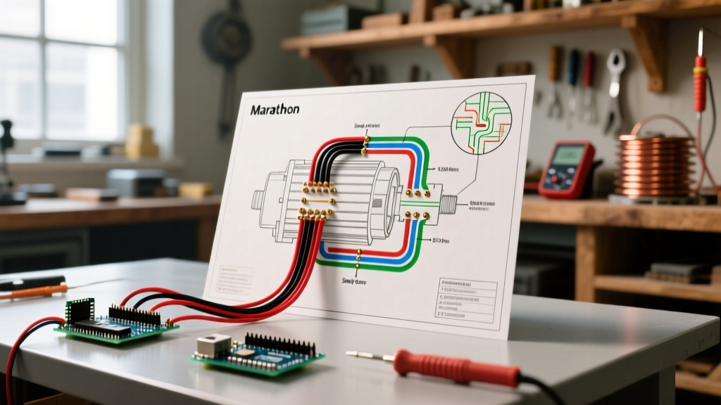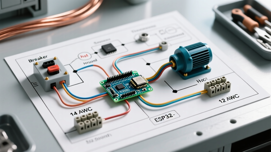

Understanding the 36V E-Bike Architecture
Building a custom electric bicycle requires more than just connecting colored wires; it demands a strict adherence to voltage tolerances, current limits, and signal logic. When working with a 36V electric bike wiring diagram, the most critical concept to grasp is that '36V' is merely the nominal voltage. In reality, a fully charged 10-series (10S) lithium-ion battery pack outputs 42V, and it will sag to roughly 30V under heavy load or near depletion. Modern 2026 sine-wave controllers, such as the KT36SVPR v2 or the Sabvoton Mini, are designed to handle this 30V-42V window, but miswiring a 12S (50.4V) pack into a strict 36V system will instantly blow the low-voltage regulator and MOSFETs.
This step-by-step walkthrough covers the complete wiring sequence for a 36V rear hub motor build using an external controller, a 10S smart BMS battery, and standard low-voltage peripherals. According to the U.S. Consumer Product Safety Commission (CPSC), improper wiring and poor solder joints are leading causes of lithium-ion e-bike fires, making precision in your harness construction non-negotiable.
Core Component Checklist & Wire Gauge Matrix
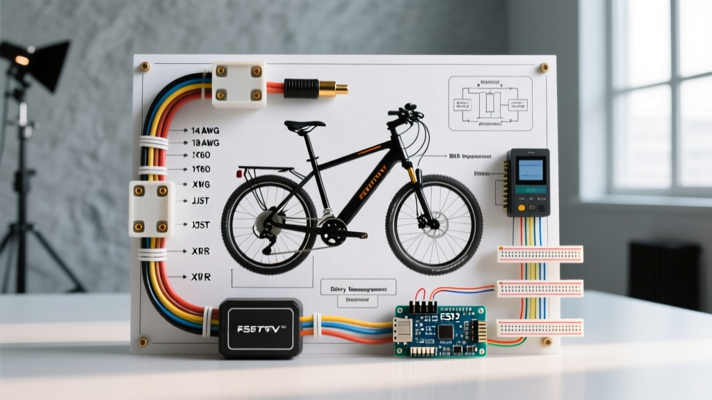
Before cutting any wire, verify your components and select the correct American Wire Gauge (AWG). Undersized wires cause voltage sag and heat buildup, while oversized wires add unnecessary weight and stiffness to the steering harness. The Engineering Toolbox Wire Gauge Chart provides the baseline, but e-bike applications require silicone-jacketed wire for high-strand flexibility and heat resistance.
| Circuit Path | Recommended Wire Gauge | Connector Type | Max Continuous Current |
|---|---|---|---|
| Battery to Controller (Main Power) | 12 AWG Silicone | Amass XT60 or XT90 | 30A - 40A |
| Controller to Motor (Phase Wires) | 14 AWG Silicone | 4mm Bullet or MR30 | 25A - 35A |
| Hall Sensors & Throttle | 20 AWG PVC / Braided | JST-SM or Higo Waterproof | < 1A (5V Logic) |
| Lighting & Accessories | 18 AWG PVC | JST-SM or Bullet 2mm | 3A - 5A |
Expert Tip: Never use standard automotive PVC wire for the main battery leads or phase wires. The heat generated near the controller terminals will melt PVC insulation, leading to dead-shorts. Always use high-strand-count silicone wire.
Step 1: Battery to Controller Main Power Routing
The main power loop is the backbone of your 36V system. We are assuming the use of a 10S battery pack equipped with a modern Bluetooth BMS (such as a JK 10S 60A Active Balancer), which allows you to monitor cell differentials via a smartphone app.
1.1 Soldering the XT60 Connector
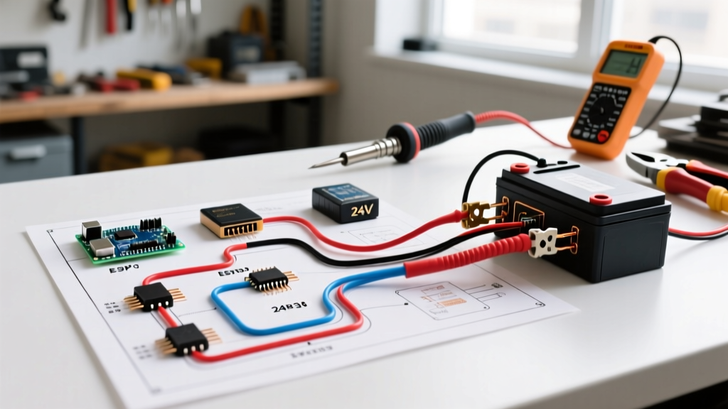
Strip exactly 7mm of insulation from your 12 AWG red and black silicone wires. Tin the wires and the XT60 solder cups separately with 63/37 rosin-core solder. When joining them, ensure the solder flows completely into the cup. A 'cold joint' looks dull and grainy; this creates high electrical resistance, which manifests as localized melting at the connector during hard acceleration.
1.2 Integrating the Anti-Spark Resistor
When you plug a 42V battery into a controller with large electrolytic capacitors, the inrush current can spike to over 100A for a few milliseconds. This causes a visible spark that slowly pits the XT60 contacts. To prevent this, solder a 100-ohm 5W power resistor in parallel with a momentary switch, or use an XT90-S (anti-spark) connector which has this resistor built-in. Connect the main battery leads to the controller's main power pigtails, covering the joints with dual-wall adhesive heat shrink tubing for waterproofing and strain relief.
Step 2: Motor Phase & Hall Sensor Integration
Wiring a 3-phase brushless DC (BLDC) hub motor requires matching both the thick phase wires and the delicate 5-wire hall sensor harness.
2.1 Phase Wire Sequencing
Connect the controller's blue, green, and yellow 14 AWG phase wires to the corresponding motor wires using 4mm bullet connectors. Wrap each connection in heat shrink, then wrap the entire bundle in friction tape or braided sleeving to prevent abrasion against the bike frame's chainstays.
2.2 The 'Learning Wire' Auto-Calibration
Color-coding between different manufacturers (e.g., Bafang, QS Motor, and generic KT controllers) is notoriously inconsistent. If the motor stutters, draws excessive current, or spins backward, do not manually swap phase wires blindly. Instead, use the controller's white learning wire. Plug the two white loop wires together, power on the system, and the controller will automatically detect the correct hall sensor phase angle (usually 60 or 120 degrees) and rotation direction. Once the motor spins smoothly in the forward direction, unplug the learning wires to lock in the configuration.
Step 3: Low-Voltage Peripheral Wiring (Throttle, PAS, Brakes)
The low-voltage harness operates on a 5V logic system regulated by the controller's internal DC-DC buck converter. Shorting any of these 5V lines to ground will instantly destroy the controller's 5V regulator, rendering the unit dead.
3.1 Throttle & PAS Pinouts
- Throttle (3-Wire): Red (5V), Black (Ground), Green/White (Signal 0.8V to 4.2V). Ensure the physical plug matches the pinout; many generic throttles reverse the red and black wires, which will short the 5V regulator.
- Pedal Assist Sensor - PAS (3-Wire): Red (5V), Black (Ground), Yellow/White (Signal). The PAS sensor relies on a magnet disc passing a Hall switch. Ensure the magnet disc is mounted 1-2mm from the sensor and that the polarity faces the correct direction (usually N-pole facing the sensor).
- E-Brakes (2-Wire): Most e-bike brake levers use a Normally Closed (NC) switch. When the lever is pulled, the circuit opens, signaling the controller to cut motor power. Wire the brake signal and ground to both left and right brake levers in parallel.
Step 4: Display & Lighting Harness Setup
Modern displays like the KT-LCD8H or Bafang DPC-18 communicate with the controller via a 5-pin or 3-pin UART/CAN-bus protocol. Do not attempt to hardwire a display by guessing the pinout; a mismatched TX/RX data line won't necessarily destroy the component, but it will result in a blank screen and error code 30 (Communication Failure).
For lighting, route the 18 AWG headlight and taillight wires to the controller's dedicated 'Light' output if available. This allows you to toggle the lights via the handlebar display. If your controller lacks a lighting output, wire the lights to the battery's secondary discharge port, ensuring you install an inline 5A automotive blade fuse to protect against a short circuit in the steering tube.
Common 36V Wiring Failure Modes & Troubleshooting
Even with a perfect 36V electric bike wiring diagram on paper, physical execution introduces variables. Here are the most common edge cases encountered in DIY builds:
1. Melted Battery Connectors (The Oxidation Trap)
Symptom: The XT60 connector melts and fuses together after a 10-mile ride, despite the system only pulling 15A.
Cause: This is rarely caused by overcurrent. It is caused by poor solder joints or oxidized brass contacts inside the connector, creating a high-resistance bottleneck. The electrical energy converts to heat precisely at the joint. Clean contacts with isopropyl alcohol and apply dielectric grease to prevent future oxidation.
2. Controller 5V Regulator Burnout
Symptom: The display turns on, but the throttle is dead, PAS doesn't engage, and the motor won't spin. A multimeter reads 0V on the red throttle wire.
Cause: A 5V-to-Ground short occurred somewhere in the peripheral harness. This frequently happens when handlebar wires are pinched against the metal stem during installation, or if a cheap aftermarket headlight back-feeds voltage into the 5V line. Always test peripheral continuity with a multimeter before plugging them into the controller.
3. Ground Loop Interference in PAS
Symptom: The motor surges erratically or engages without pedaling when the headlight is turned on.
Cause: High current from the lighting circuit is bleeding into the low-voltage PAS signal ground. To fix this, ensure all sensor grounds return directly to the controller's main ground plane, rather than daisy-chaining grounds through the lighting circuit.
Frequently Asked Questions
Can I use a 48V battery on a 36V controller?
No. A 48V (13S) battery charges to 54.6V. Most strict 36V controllers have capacitor voltage ratings of 50V or 63V. Pushing 54.6V into a 50V-rated system will cause catastrophic capacitor failure and MOSFET shorting. Furthermore, as noted in Battery University's guide on series configurations, the BMS cutoff voltages will not align with the controller's Low Voltage Cutoff (LVC), risking deep-discharge damage to the battery cells.
What is the correct wire sequence for a 36V hub motor?
There is no universal color standard for 3-phase BLDC motors. While Yellow, Green, and Blue are common, the internal hall sensor angles (60 vs 120 degrees) dictate the true sequence. Always rely on the controller's auto-learn feature or a multimeter to verify hall sensor logic states rather than trusting wire jacket colors.
How do I waterproof the wiring harness?
Use Higo (also known as Julet) waterproof connectors for all external peripheral connections. For the main controller box, route all wires out of the bottom of the enclosure to create a 'drip loop,' preventing water from wicking down the wires and into the terminals via capillary action.