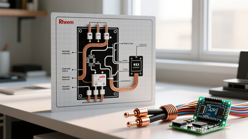

Introduction to GM Delco Alternators in DIY Appliance Power
When building custom off-grid power systems, motorized shop appliances, or heavy-duty 12V DC compressor fridges, the GM Delco Remy 10-SI and 12-SI alternators remain the undisputed champions of DIY power generation. Despite the automotive industry shifting toward advanced LIN-bus controlled alternators, the robust, internally regulated SI series (produced primarily from the 1970s through the late 1980s, and still remanufactured today) offers unparalleled simplicity for custom appliance wiring. As of 2026, with the mass adoption of 12V LiFePO4 smart battery management systems (BMS) in off-grid setups, understanding the exact wiring diagram for GM alternator integration is critical to prevent overcharging and protect sensitive appliance PCBs.
Whether you are wiring a standalone generator head to power a 12V welding rig or replacing the charging system in a custom vehicle build, choosing between a 1-wire and 3-wire configuration dictates the efficiency and safety of your entire electrical ecosystem.
Decoding the Delco 10-SI and 12-SI Terminals
Before cutting any wire, you must understand the physical layout of the Delco SI rear housing. Unlike modern alternators that require a dedicated ECU signal, the SI series relies on a simple three-terminal topology:
- BAT (Battery) Terminal: The large threaded stud on the back. This is your main DC output. It connects directly to the battery positive or your main appliance distribution busbar.
- Terminal #1 (Exciter/Indicator): This smaller spade terminal serves two purposes. First, it receives the initial 12V 'excitation' current to turn the alternator on. Second, it grounds through an internal circuit to illuminate a dashboard 'ALT' or 'GEN' warning light if the alternator fails to produce voltage.
- Terminal #2 (Voltage Sense): This terminal tells the internal voltage regulator the exact voltage at the battery or appliance load. By sensing voltage at the destination rather than at the alternator housing, the regulator compensates for voltage drop across long wire runs.
The 3-Wire Wiring Diagram for GM Alternator (Optimal for Sensitive Appliances)
The 3-wire setup is the factory-standard configuration and the highly recommended method when powering sensitive DIY appliances, such as 12V variable-speed water pumps, lithium battery chargers, or digital control boards. It ensures precise voltage regulation and immediate alternator engagement at idle.
Step-by-Step 3-Wire Integration
- Main Output (BAT): Run a heavy-gauge wire (see sizing table below) from the BAT stud to the positive terminal of your battery bank or main DC busbar. Always install an inline ANL or Class-T fuse rated 120% of the alternator's maximum output.
- Voltage Sense (Terminal #2): Run an 18 AWG or 16 AWG wire from Terminal #2 directly to the positive battery post or the positive side of your BMS shunt. Do not connect this to the BAT stud on the alternator; doing so defeats the purpose of remote sensing.
- Exciter Circuit (Terminal #1): Run an 18 AWG wire from Terminal #1 to a switched 12V ignition source. To protect the internal regulator and provide the correct initial resistance, wire a 10-ohm, 2-watt resistor in parallel with a standard 194 incandescent indicator bulb. When the ignition switches on, current flows through the bulb/resistor, exciting the rotor field. Once the alternator begins generating power, internal diodes back-feed the circuit, turning off the dash light.
Expert Warning: Never use an LED bulb for the Terminal #1 indicator circuit without adding a parallel bypass resistor. LEDs draw insufficient current to excite the Delco SI rotor field, resulting in an alternator that will not 'turn on' until the engine is revved to high RPMs.
The 1-Wire Conversion Diagram (Simplified Off-Grid Setup)
For rugged, non-sensitive appliance loads—such as powering a 12V winch, a basic DC cooling fan array, or a simple lead-acid battery bank—the 1-wire setup is a popular DIY shortcut. Many aftermarket 10-SI and 12-SI alternators are sold pre-configured for 1-wire operation, utilizing an internal jumper wire connected to a specialized sensing diode.
How the 1-Wire Jumper Works
In a 1-wire diagram, Terminal #1 is physically jumpered to the BAT stud on the rear of the alternator. Terminal #2 is either left disconnected or jumpered to the BAT stud (depending on the specific aftermarket regulator installed). When the engine turns, the residual magnetism in the rotor, combined with the direct connection to the battery voltage via the jumper, excites the field.
Pros and Cons of 1-Wire Configurations
| Feature | 1-Wire Setup | 3-Wire Setup |
|---|---|---|
| Wiring Complexity | Extremely Low (1 cable) | Moderate (3 distinct circuits) |
| Idle Engagement | Poor (Often requires 'revving' to excite) | Excellent (Engages immediately at idle) |
| Voltage Drop Compensation | None (Senses at the alternator housing) | High (Senses at the battery/load) |
| Appliance Safety | Low (Risk of overcharging at the battery) | High (Precise regulation) |
Wire Gauge Selection for High-Draw Appliance Loads
Undersizing the BAT wire is the most common cause of alternator failure in DIY builds. Voltage drop generates heat, which degrades the internal stator windings and destroys the rectifier diode trio. According to the National Electrical Code (NFPA 70), you must also account for temperature derating in high-heat engine bays or enclosed generator housings.
Alternator Output Wire Sizing Matrix (Copper Wire, 12V DC)
| Alternator Model / Output | Max Amperage | Recommended AWG (Up to 5 ft) | Recommended AWG (5 to 15 ft) |
|---|---|---|---|
| Delco 10-SI (Standard) | 63A - 80A | 8 AWG | 6 AWG |
| Delco 12-SI (Heavy Duty) | 94A - 110A | 6 AWG | 4 AWG |
| Delco 15-SI / High Output | 130A - 145A | 4 AWG | 2 AWG |
| Custom 1-Wire High Output | 150A - 200A+ | 2 AWG | 1/0 AWG |
Note: Always use pure copper, fine-stranded marine-grade wire (e.g., THHN or welding cable) rather than Copper-Clad Aluminum (CCA) to minimize resistance and prevent terminal corrosion.
Troubleshooting Common Failure Modes in Appliance Setups
When integrating a GM alternator into a custom appliance or off-grid power matrix, specific failure modes emerge that standard automotive mechanics rarely encounter.
1. AC Ripple Destroying Appliance PCBs
The alternator's rectifier assembly converts AC stator output to DC. If one or more of the six internal diodes fail, raw AC voltage 'ripples' into your DC system. While a standard car starter motor won't notice, a 12V compressor fridge or a lithium BMS will suffer catastrophic logic board failure. According to diagnostic standards outlined by AA1Car automotive electrical guidelines, AC ripple should never exceed 50mV to 100mV. Test this by setting a multimeter to AC Volts, placing the probes on the BAT terminal and ground while the system is under load.
2. Exciter Circuit Back-Feed
If your custom appliance setup lacks a traditional ignition switch, you might wire Terminal #1 to a manual toggle switch. If you forget to turn this switch off when the engine stops, the alternator's internal diode trio will back-feed 12V power from the BAT terminal, through the regulator, and out through Terminal #1. This parasitic draw will completely drain your battery bank overnight and burn out the regulator.
3. Sense Wire Voltage Drop Overcharge
If the 18 AWG wire connected to Terminal #2 breaks or develops high resistance due to corrosion, the internal regulator assumes the battery voltage is near zero. It will respond by commanding the alternator to output maximum voltage (often 15.5V or higher) in a futile attempt to reach the target 14.2V. This will rapidly boil lead-acid batteries and trigger high-voltage disconnects on lithium BMS units, leaving your appliances without power.
Final Integration Notes for 2026 Builds
As the DIY off-grid and custom appliance market continues to evolve, pairing legacy hardware like the Delco 10-SI with modern power electronics requires respect for foundational electrical principles. While the U.S. Department of Energy notes that modern vehicle alternator outputs have surged past 200A to handle advanced ADAS and infotainment systems, the humble 94-amp 12-SI remains the most cost-effective, easily repairable DC power plant for custom 12V appliance builders. By strictly adhering to the 3-wire diagram, utilizing proper AWG cabling, and protecting your sense circuits, you can build a charging system that reliably powers your custom appliances for decades.