
Understanding the Wiring Diagram for Schumacher Battery Chargers
While most consumer-grade battery chargers are treated as simple plug-and-play devices, maintaining, repairing, or hardwiring a Schumacher unit requires a precise understanding of its external and internal electrical pathways. Whether you are replacing a frayed AC power cord on a Schumacher SC1325 25-Amp Smart Charger, upgrading the DC clamp cables on a heavy-duty SE-4022 40-Amp Transformer Model, or hardwiring a marine-grade unit into an RV DC bus, referencing the correct wiring diagram for Schumacher battery charger configurations is critical. Incorrect wire gauge selection or misapplied color codes can lead to premature charge termination, thermal runaway, or severe fire hazards.
This comprehensive reference guide breaks down the exact wire gauge (AWG) requirements, voltage drop tolerances, and SAE/ABYC color code standards necessary to safely service and modify Schumacher charging systems in 2026.
Anatomy of the External Wiring Schematic
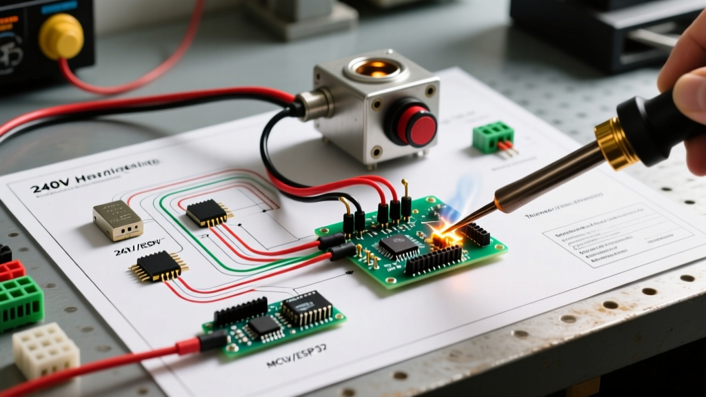
A standard Schumacher smart charger operates on a dual-circuit topology: a high-voltage AC input stage and a low-voltage, high-current DC output stage. The microcontroller unit (MCU) inside modern Schumacher switch-mode chargers relies on highly accurate voltage sensing at the battery terminals. If the wiring between the charger's internal rectifier and the battery clamps introduces unexpected resistance, the MCU will misinterpret the battery's state of charge (SoC).
The AC Input Stage (120V/240V)
The AC input wiring connects the wall outlet to the charger's internal transformer or switching power supply. For standard 120V North American models (like the SC1305 or SC1325), the input is typically a NEMA 5-15P plug attached to an SJTW or SVT flexible cord. When replacing this cord, you must adhere to NFPA 70 (National Electrical Code) standards for flexible cord ampacity and grounding.
The DC Output Stage (12V/24V)
The DC output side carries the bulk of the current. A 40-amp charger like the SE-4022 pushes massive current through the DC cables. Unlike the AC side, where skin effect and alternating current dynamics apply, the DC side suffers strictly from ohmic resistance. This makes the physical cross-sectional area of the copper wire the single most important factor in your wiring diagram.
Wire Gauge (AWG) Selection & The Voltage Drop Factor
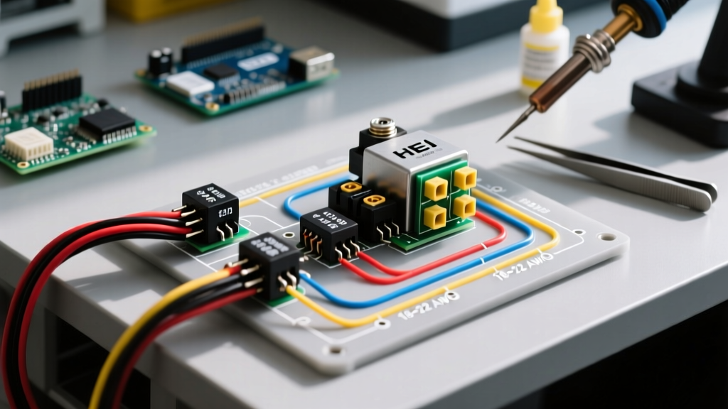
The most common mistake DIYers make when extending or replacing DC charging cables is using undersized wire. Modern Schumacher smart chargers utilize a multi-stage charging algorithm (Bulk, Absorption, Float). The transition from Bulk to Absorption occurs when the battery voltage reaches a specific threshold (usually around 14.4V to 14.8V for AGM/Flooded lead-acid).
Expert Insight: If you use 12 AWG wire to extend a 25-Amp charger's DC cables by 10 feet, the wire resistance will cause a voltage drop of approximately 0.8V at peak current. The charger's MCU will read 14.4V at its internal terminals while the battery is only receiving 13.6V. The charger will prematurely terminate the Bulk phase, leaving your battery chronically undercharged and prone to sulfation.
DC Cable Sizing Matrix for Schumacher Chargers
The following table dictates the minimum stranded copper wire gauge required for DC output extensions based on the charger's maximum amperage and the total round-trip cable length (Positive + Negative).
| Charger Max Output | Under 5 ft (Total) | 5 ft to 15 ft (Total) | 15 ft to 30 ft (Total) | Over 30 ft (Total) |
|---|---|---|---|---|
| 6A - 12A (e.g., SC1306) | 14 AWG | 12 AWG | 10 AWG | 8 AWG |
| 15A - 25A (e.g., SC1325) | 10 AWG | 8 AWG | 6 AWG | 4 AWG |
| 30A - 40A (e.g., SE-4022) | 8 AWG | 4 AWG | 2 AWG | 1/0 AWG |
| 50A+ (Engine Start Mode) | 4 AWG | 2 AWG | 1/0 AWG | 2/0 AWG |
Note: Always use fine-strand, high-purity copper wire (such as SAE J1128 or marine-grade tinned copper). Avoid Copper-Clad Aluminum (CCA) wire, as it possesses 60% higher resistance and is a known fire hazard in high-current DC applications.
Standard Color Codes: AC vs. DC vs. Marine
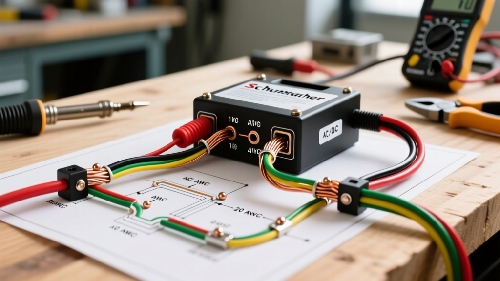
Confusing AC color codes with DC color codes is a frequent cause of catastrophic short circuits. When interpreting a wiring diagram for Schumacher battery charger repairs, you must apply the correct standard based on which side of the transformer you are working on.
1. AC Input Wiring (US NEC Standard)
For the 120V AC power cord entering the charger chassis, follow standard US household wiring colors:
- Black (or Red): Line / Hot (Connects to the fuse or primary switch)
- White: Neutral (Connects to the common return path)
- Green (or Bare Copper): Earth Ground (Must be bonded to the charger's metal chassis or dedicated grounding lug)
2. Automotive DC Output (SAE Standard)
For standard garage and automotive applications, the Society of Automotive Engineers (SAE) dictates the following for the DC clamp cables:
- Red: DC Positive (+) (Routes to the red alligator clamp or ring terminal)
- Black: DC Negative (-) (Routes to the black alligator clamp or chassis ground)
3. Marine & RV DC Wiring (ABYC E-11 Standard)
If you are hardwiring a Schumacher marine charger (like the SC1308) into a boat's DC distribution panel, the American Boat and Yacht Council (ABYC) requires different color codes to prevent confusion with AC shore power wiring:
- Red: DC Positive (+)
- Yellow (or Black with Yellow Stripe): DC Negative (-)
Warning: Never use Green for DC negative in a marine environment, as Green is strictly reserved for AC Earth Ground and bonding systems.
Step-by-Step: Hardwiring an Onboard Schumacher Marine Charger
When permanently installing an onboard Schumacher charger, you bypass the standard AC plug and DC clamps, wiring the unit directly to the vessel's AC shore-power breaker and DC bus bars.
- AC Shore Power Connection: Run a 12 AWG (minimum) marine-grade triplex cable from a dedicated 15A or 20A AC breaker panel to the charger's AC terminal block. Connect Black to Hot, White to Neutral, and Green to the AC Grounding bus.
- DC Positive Routing: Connect a Red 6 AWG (or larger) marine wire from the charger's DC+ output to the positive DC bus bar. Crucial Step: Install an inline ANL or Class-T fuse within 7 inches of the positive bus bar connection to protect against short circuits, as mandated by ABYC E-11.
- DC Negative Routing: Connect a Yellow 6 AWG wire from the charger's DC- output to the negative DC shunt or bus bar.
- Chassis Grounding: Bond the charger's metal mounting flanges or dedicated chassis ground stud to the vessel's main DC grounding bus using a minimum 8 AWG green wire.
Common Wiring Failure Modes & Troubleshooting
Even with a correct wiring diagram, environmental factors and poor termination techniques can cause Schumacher chargers to throw error codes. Here are the most common wiring-related failure modes:
1. The "Check Battery" or Flashing Red LED Error
Cause: High resistance on the DC negative cable. If the negative clamp is attached to a painted chassis ground rather than directly to the battery's negative post, the voltage drop confuses the MCU's impedance testing algorithm.
Fix: Always connect the black DC clamp directly to the battery's negative terminal for the most accurate smart-charging diagnostics.
2. Thermal Shutdown (Overheating Cables)
Cause: Using CCA (Copper-Clad Aluminum) wire or undersized AWG for the DC output. The cables will physically heat up, and the heat can travel via conduction into the charger's internal rectifier, triggering the thermal protection shutoff.
Fix: Verify wire material with a wire stripper (CCA reveals a silver/aluminum core when scratched). Replace with 100% stranded copper.
3. AC Ground Fault Interruption (GFCI Tripping)
Cause: Internal moisture ingress or a pinched AC neutral wire touching the chassis ground inside the charger casing.
Fix: Open the chassis, inspect the AC SVT cord strain relief, and ensure the white neutral wire is not making contact with any metallic components or the green ground wire.
Expert Safety Protocols & Final Verdict
Modifying or repairing the wiring on a Schumacher battery charger bridges the gap between high-voltage AC safety and high-current DC physics. Always disconnect the AC power before opening the chassis, and use a multimeter to verify that the internal filter capacitors have discharged to below 10V before touching any internal AC spade connectors.
By strictly adhering to the proper wire gauge matrices and respecting the distinct color codes for AC, Automotive DC, and Marine DC systems, you ensure that your Schumacher charger operates at peak efficiency, delivering the exact voltage and current profiles required to maximize your battery's lifespan. For further reading on electrical safety standards, consult the Schumacher Electric Official Support Center for model-specific schematics and firmware behaviors.