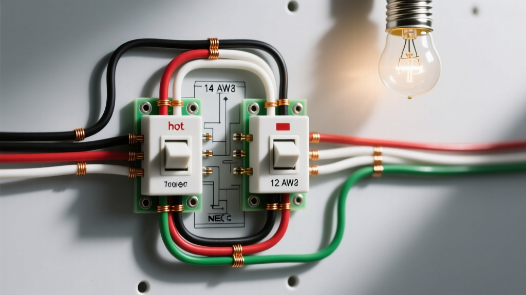

Mastering the Wiring Diagram for Two Switches One Light
Controlling a single light fixture from two separate locations is a fundamental residential electrical configuration, commonly found in stairwells, hallways, and large living spaces. While finding a standard wiring diagram for two switches one light (technically known as a 3-way switch circuit) is relatively easy, many DIYers and junior electricians fail to account for the critical nuances of wire gauge selection and National Electrical Code (NEC) color code compliance. Misidentifying traveler wires or undersizing your conductors doesn't just lead to a malfunctioning circuit; it creates a severe fire hazard and guarantees a failed municipal inspection.
In this comprehensive reference guide, we bridge the gap between theoretical diagrams and practical, code-compliant installation. We will break down the exact wire gauges required for 15-amp and 20-amp lighting circuits, decode the NEC color mandates for traveler and neutral conductors, and outline the specific cable types you need to pull from the panel to the final fixture.
Wire Gauge Selection: 14 AWG vs. 12 AWG for Lighting Circuits
The foundation of any safe wiring diagram for two switches one light begins at the circuit breaker. The gauge of the wire you use is strictly dictated by the amperage rating of the overcurrent protection device (the breaker). According to NFPA 70 (NEC) Article 310.16, conductors must possess an ampacity that matches or exceeds the breaker rating.
For residential lighting, you will almost exclusively choose between 14 AWG and 12 AWG copper conductors. While 14 AWG is thinner, easier to bend in crowded switch boxes, and cheaper, it is strictly limited to 15-amp breakers. If your lighting circuit is tied to a 20-amp breaker (which is increasingly common in modern 2026 construction to accommodate smart home hubs and high-draw LED arrays), you must use 12 AWG wire.
Wire Gauge & Breaker Sizing Matrix
| Breaker Size | Min. Wire Gauge | Cable Type (w/ Ground) | Max Continuous Load | Approx. 2026 Material Cost |
|---|---|---|---|---|
| 15 Amp | 14 AWG | NM-B 14/3 | 1,440 Watts (120V) | $0.65 - $0.80 / linear ft |
| 20 Amp | 12 AWG | NM-B 12/3 | 1,920 Watts (120V) | $0.95 - $1.15 / linear ft |
Note: For a 3-way switch setup, you must use 3-conductor cable with a ground (e.g., Southwire Romex SIMpull 14/3 or 12/3 NM-B) between the two switches to accommodate the two traveler wires and the neutral/line continuation.
NEC Color Code Compliance for Travelers and Neutrals
The most common point of failure when executing a wiring diagram for two switches one light is the misidentification of the "traveler" wires. In a 3-way switch setup, the travelers carry the electrical current between the two switches depending on their toggle positions. The NEC has strict rules regarding wire coloring to prevent lethal shock hazards during future maintenance.
Standard Color Assignments for 3-Way Circuits
- Ground: Bare copper or green. Must be pigtailed to the metal switch box (if applicable) and the green grounding screw on both 3-way switches.
- Neutral: White or gray. Crucial Update: Under NEC Article 404.2(C), a neutral conductor is now mandatory at nearly all switch boxes to accommodate smart switches, timers, and occupancy sensors. The neutral bypasses the 3-way switch mechanism and connects directly to the light fixture, but it must be present in the box and capped with a wire nut if not in use.
- Line (Power Source): Black. This is the always-hot wire bringing power from the breaker panel to the common terminal of the first 3-way switch.
- Load (Switched Leg): Black or Red. This wire carries the switched power from the common terminal of the second 3-way switch up to the light fixture.
- Travelers: Typically Red and Black (when using standard 3-conductor NM-B cable). These connect to the brass-colored traveler terminals on both switches. They are interchangeable; there is no "Traveler 1" or "Traveler 2".
The Re-Identification Rule (NEC 200.7)
In certain wiring topologies—specifically when power enters at the light fixture and drops down to the first switch via a 2-conductor cable—the white wire in that cable must be used as a hot "Line" or "Load" conductor. The NEC strictly prohibits using a white wire as a hot conductor unless it is permanently re-identified. You must wrap the white wire with black or red electrical tape (or use heat-shrink tubing) at both ends to signal to future electricians that this wire is carrying live voltage, not serving as a neutral.
Step-by-Step Wiring Sequence: Power at the First Switch
To translate the wiring diagram for two switches one light into physical reality, let's examine the most common and code-compliant routing method: Power enters at Switch 1, travels to Switch 2, and then routes up to the light fixture.
Step 1: The Panel to Switch 1 (Line & Neutral)
Run a standard 2-conductor cable (14/2 or 12/2 NM-B) from the breaker panel to the first switch box.
Action: Connect the bare ground to the box and switch. Connect the white neutral to the bundle of neutrals passing through to the light. Connect the black line wire to the Common Terminal (usually the dark-colored screw) on the first 3-way switch.
Step 2: Switch 1 to Switch 2 (The Travelers & Neutral)
Run a 3-conductor cable (14/3 or 12/3 NM-B) between the two switch boxes.
Action: Connect the bare ground. Connect the white wire to the neutral bundle (satisfying the NEC 404.2(C) smart-switch requirement). Connect the red and black wires to the two brass Traveler Terminals on Switch 1, and route them to the brass Traveler Terminals on Switch 2.
Step 3: Switch 2 to the Light Fixture (The Switched Leg)
Run a 2-conductor cable (14/2 or 12/2 NM-B) from the second switch box up to the ceiling canopy.
Action: Connect the black wire to the Common Terminal on Switch 2. This wire becomes the "Switched Leg" (Load) and connects to the black (hot) wire on the light fixture. Connect the white wire to the neutral bundle in the switch box, and route it up to the white (neutral) wire on the light fixture.
Expert Insight: Smart Switch Upgrades
If you plan to install a smart 3-way switch system (like the Leviton Decora Smart Wi-Fi 3-Way), the master switch requires a dedicated line, neutral, and load, while the companion switch requires a traveler and neutral. Failing to pull a neutral wire to both switch boxes during the rough-in phase will render modern smart switches completely inoperable. Always pull 3-conductor cable between switches, even if a basic mechanical diagram only requires 2-conductor.
Troubleshooting Common Wire Gauge & Color Code Errors
Even seasoned professionals occasionally make errors when interpreting complex 3-way topologies. Here are the most frequent failure modes and how to resolve them using a multimeter and NEC guidelines.
1. The Breaker Trips Immediately
Cause: A dead short, often caused by mixing up the neutral and a traveler wire, or using 14 AWG wire on a 20-amp circuit that is experiencing an inrush current spike from a large transformer-based LED driver.
Fix: Verify breaker sizing. Ensure all white wires acting as neutrals are isolated from the brass traveler terminals.
2. The Light Only Works from One Switch
Cause: The "Line" or "Load" wire has been mistakenly connected to a brass traveler terminal instead of the black Common terminal.
Fix: Identify the common terminal (it is physically distinct on the switch, often labeled "COM" or colored black/dark bronze). The single hot source and the single switched leg must exclusively occupy these terminals.
3. Voltage Drop and Flickering Lights
Cause: Using 14 AWG wire on an excessively long run (over 50 feet) combined with a high-wattage load, resulting in a voltage drop below 110V at the fixture.
Fix: Consult Mike Holt's NEC voltage drop recommendations. For runs exceeding 50 feet on a 15-amp circuit, upgrade to 12 AWG wire to mitigate resistance and ensure consistent lumen output from LED fixtures.
Frequently Asked Questions (FAQ)
Can I use 14/2 wire between the two 3-way switches?
No. A standard wiring diagram for two switches one light requires two traveler wires to bridge the switches. A 14/2 cable only provides one black and one white wire. Using the white wire as a second traveler violates NEC color codes and leaves you without a dedicated neutral in the second switch box, which violates NEC 404.2(C). You must use 14/3 or 12/3 cable.
Does it matter which brass traveler screw gets the red or black wire?
No. The traveler terminals on a 3-way switch are electrically symmetrical. The internal toggle mechanism simply bridges the common terminal to one traveler or the other. You can swap the red and black traveler wires on either switch without affecting the circuit's logical operation.
What if my old house has no ground wire in the switch box?
According to OSHA and NEC retrofit guidelines, if you are replacing an existing 3-way switch in an ungrounded box, you must use a GFCI-protected breaker or a specialized GFCI 3-way switch setup to provide shock protection, as a standard equipment grounding conductor cannot be artificially created without pulling new cable back to the panel.
Final Verification Before Energizing
Before flipping the breaker to the "ON" position, perform a continuity test with a multimeter. Ensure there is zero continuity between the hot line and the ground, and between the hot line and the neutral. Once verified, energize the circuit and test all four toggle combinations of the two switches. A correctly executed wiring diagram for two switches one light will allow the light to be toggled on or off from either location, regardless of the other switch's position. By strictly adhering to 14/12 AWG gauge limits and NEC color re-identification rules, you ensure a circuit that is not only functional but inherently safe and fully compliant with modern electrical standards.