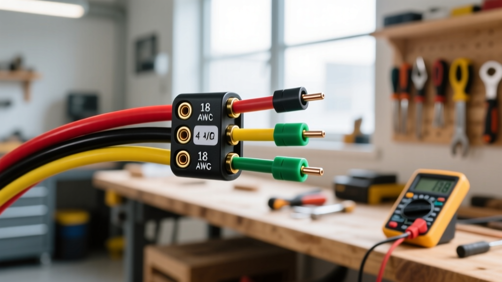

Understanding the Standard 4-Way Flat Connector
When working with light-duty utility trailers, boat trailers, and small campers, the 4-way flat connector remains the undisputed industry standard. If you are searching for a reliable wiring diagram for a 4 wire trailer, you are likely dealing with a setup that requires tail lights, brake lights, and left/right turn signals, but does not require auxiliary power or electric brake controllers. Despite its simplicity, improper wiring or poor grounding accounts for over 80% of all trailer lighting failures on the road today.
This comprehensive reference guide breaks down the exact pinout, wire gauge requirements, and modern troubleshooting techniques for 2026 vehicle builds, ensuring your trailer remains compliant with federal lighting regulations and functions flawlessly behind modern vehicles equipped with sensitive Body Control Modules (BCMs).
The 4-Wire Trailer Pinout Diagram & Specifications
The 4-way flat connector utilizes a standardized color code established by the Society of Automotive Engineers (SAE) and enforced under federal safety guidelines. Below is the definitive pinout matrix for both the vehicle-side (male) and trailer-side (female) connectors.
| Pin Position | Wire Color | Circuit Function | Recommended Gauge (Up to 20ft) | Recommended Gauge (20ft+) |
|---|---|---|---|---|
| Pin 1 (Exposed/Outer) | White | Chassis Ground | 14 AWG | 12 AWG |
| Pin 2 | Brown | Tail / Running / License Plate | 16 AWG | 14 AWG |
| Pin 3 | Yellow | Left Turn Signal & Brake | 16 AWG | 14 AWG |
| Pin 4 | Green | Right Turn Signal & Brake | 16 AWG | 14 AWG |
Expert Insight: Never use the trailer hitch ball as your primary ground path. According to Federal Motor Carrier Safety Administration (FMCSA) Section 393.11, all lighting devices must have a dedicated, low-resistance ground to the vehicle chassis. Relying on the hitch ball leads to intermittent grounding, especially on boat trailers with rusted hinges or aluminum frames.
Step-by-Step Wiring Procedure for a 4-Wire Harness
Building or repairing a 4-wire harness requires more than just twisting wires together. Modern towing demands weather-sealed connections to prevent galvanic corrosion.
1. Harness Routing and Preparation
Use SAE J1128 compliant bonded trailer wire (often sold as a 4-conductor flat ribbon cable). For a standard 5x8 utility trailer, a 25-foot spool of 16 AWG bonded wire costs between $18 and $24. Route the harness along the inside of the trailer frame rails, securing it with UV-resistant nylon zip ties every 12 to 18 inches. Keep the wiring at least 2 inches away from exhaust components and moving suspension parts.
2. Stripping and Crimping
Strip exactly 5/16 of an inch of insulation from the wire ends. Do not use standard vinyl-insulated butt connectors; they trap moisture and fail within a single season. Instead, use adhesive-lined, dual-wall heat shrink butt connectors (e.g., 3M Scotchlok or equivalent).
- Insert the wire into the connector barrel until it hits the internal stop.
- Use a dedicated ratcheting crimping tool (like the Titan 11210 or Knoweasy equivalent, priced around $25) to apply uniform pressure.
- Apply heat using a heat gun set to 250°F (120°C) until the adhesive melts and seals the wire entry points.
3. Grounding to the Frame
For the white ground wire, attach a #10 ring terminal. Sand the trailer frame down to bare, shiny metal at the grounding point. Apply a thin layer of dielectric grease over the terminal after tightening the self-tapping screw or bolt to prevent future oxidation.
Critical Failure Modes and Troubleshooting
Even with a perfect wiring diagram for a 4 wire trailer, real-world variables introduce complex failure modes. Here is how to diagnose the most common issues encountered in the field.
The LED Hyperflash and BCM Rejection Problem
If you are upgrading from incandescent bulbs to modern LED trailer lights (such as the Optronics STL72RB series), you will drastically reduce the amperage draw on the turn signal circuits. While incandescent bulbs draw roughly 2.1 amps each, LEDs draw less than 0.5 amps.
Modern vehicles (2018 and newer) use the Body Control Module (BCM) to monitor circuit resistance. When the BCM detects the low draw of LEDs, it assumes a bulb is blown and triggers a dashboard warning, cuts power to the circuit, or causes the lights to hyperflash. The Fix: Install a 50-watt, 6-ohm load resistor (e.g., Putco 99250, approx. $12 per pair) in parallel on the yellow and green turn signal wires. Alternatively, if your tow vehicle uses a standalone tow module, upgrade to an LED-specific flasher relay.
Voltage Drop on Long Trailers
If your tail lights appear dim but your turn signals function normally, you are experiencing voltage drop. The brown wire powers all running lights and the license plate light. On trailers exceeding 20 feet, 16 AWG wire cannot sustain the required voltage over the distance. Use a Southwire Voltage Drop Calculator to verify your circuit. If voltage drops below 11.5V at the furthest fixture, you must upgrade the main brown harness run to 14 AWG or 12 AWG, stepping down to 16 AWG only for the final pigtails to the individual lights.
Backfeeding and Ground Bleed
A classic symptom of a bad ground is 'bleed-over': when you hit the left turn signal, the right turn signal and tail lights also flash dimly. This happens because the left turn circuit is seeking a path to ground through the filaments of the other bulbs. Do not add more grounds to the light fixtures. Instead, fix the primary white ground wire at the trailer tongue and ensure the vehicle-side 4-way connector is grounded directly to the tow vehicle's chassis, not just spliced into a tail light housing.
Upgrading and Adapter Scenarios
While the 4-way flat is ubiquitous, you may eventually need to interface with different systems.
- 4-Way Flat to 7-Way RV Blade: If you are towing a trailer with electric brakes but your vehicle only has a 4-pole flat, you will need an adapter (like the Curt 57187, approx. $25) AND a separate brake controller installation kit. The 4-way adapter only passes lighting signals; it does not magically activate electric brakes.
- 4-Way Flat to 4-Way Round: Common in agricultural and older motorcycle trailers. Use a Hopkins 47185 adapter. Ensure you verify the pinout on the round connector, as older agricultural trailers sometimes swap the green and yellow pins compared to the SAE flat standard.
Frequently Asked Questions
Can I use a 5-way flat connector on a 4-wire trailer?
Yes. A 5-way flat connector includes all four standard pins plus a fifth pin (usually blue) for electric reverse lockout solenoids on boat trailers. You can plug a 4-way flat trailer directly into a 5-way vehicle connector; the fifth pin will simply remain unused and should be capped to prevent corrosion.
Why does my trailer blow the vehicle's turn signal fuse when I plug it in?
This indicates a dead short to ground on either the yellow or green wire. Inspect the trailer tongue area where the harness passes through the frame. The insulation often rubs raw against sharp steel edges during transit, causing the copper to contact the frame and instantly blow the 10A or 15A BCM fuse in your tow vehicle.
Are there specific lighting standards I must follow?
Yes. All trailer lighting must comply with NHTSA FMVSS 108, which dictates the required candela output, placement, and color of all automotive lamps. Ensure any replacement LED or incandescent fixtures you purchase are explicitly stamped with 'DOT SAE' compliance markings.
Final Verification Checklist
Before taking your newly wired trailer on the road, perform this 5-point verification:
- Verify the white ground wire is secured to bare metal on both the vehicle and trailer frames.
- Test the brown wire: Turn on headlights; all marker and tail lights should illuminate steadily.
- Test the yellow wire: Left turn signal and left brake light should flash in unison.
- Test the green wire: Right turn signal and right brake light should flash in unison.
- Check for voltage drop using a multimeter at the furthest light fixture while the running lights are active (should read >11.8V).