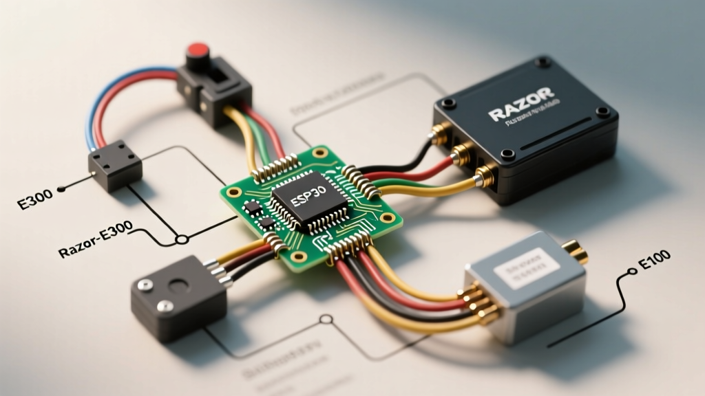

Decoding the Razor Electric Scooter Wiring Diagram
Whether you are troubleshooting a dead motor, replacing a fried speed controller, or planning a lithium-ion battery upgrade, understanding the exact razor electric scooter wiring diagram is the first step to a successful repair. The Razor E300 and E100 platforms dominate the entry-level electric mobility market, relying on a robust but straightforward 24V Sealed Lead Acid (SLA) electrical architecture.
In this comprehensive vehicle-specific guide, we will dissect the 24V harness, map the speed controller pinouts, and provide actionable multimeter diagnostics for the most common failure modes. We will also cover the wiring modifications required to safely upgrade the stock SLA setup to a modern 36V lithium system in 2026.
Safety Warning: Always disconnect the main battery harness and remove the inline fuse before probing the controller terminals. A short circuit across the 12 AWG main power leads can instantly weld metal and cause severe SLA battery venting. Adhere to NFPA 70: National Electrical Code (NEC) guidelines regarding battery ventilation and overcurrent protection.
Core Architecture of the 24V SLA System
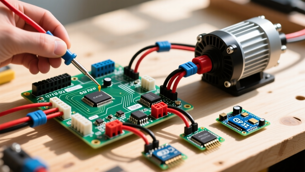
The stock Razor E300 utilizes two 12V 9Ah AGM (Absorbent Glass Mat) SLA batteries wired in series to produce a nominal 24V (25.4V fully charged). The wiring harness relies on heavy-gauge wire for high-current paths and lightweight signal wire for user inputs.
- Main Power Leads: 12 AWG stranded copper (Red/Black) routed through a 30A inline blade fuse.
- Motor Leads: 14 AWG stranded copper (Blue/Yellow) connecting the controller to the 250W brushed DC motor.
- Signal/Control Wires: 22-24 AWG (White, Green, Orange) handling throttle telemetry and brake inhibit signals.
Speed Controller Pinout Matrix
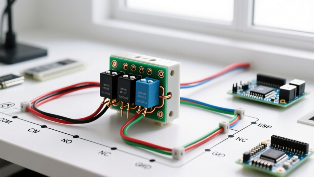
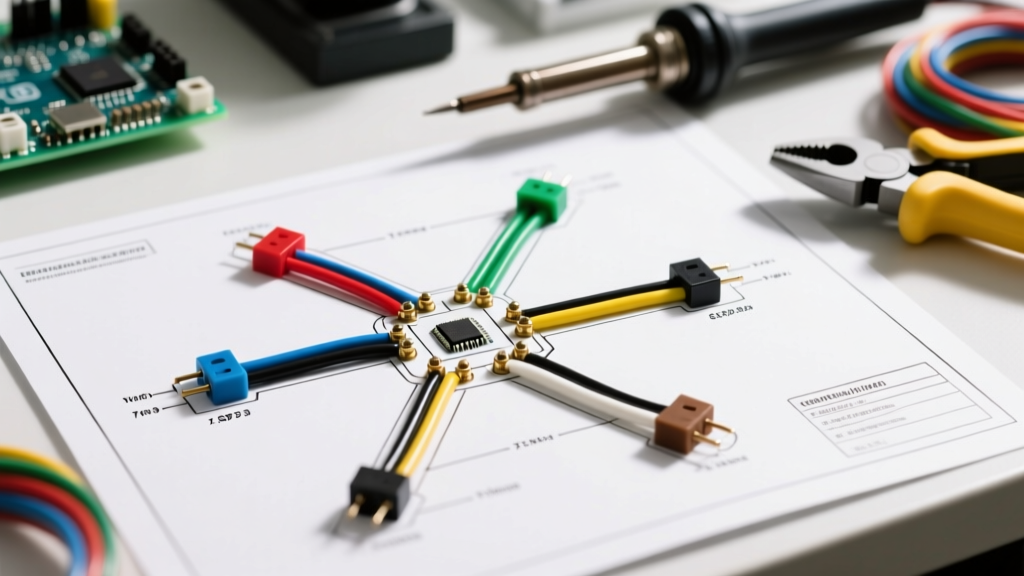
The heart of the scooter is the brushed DC speed controller. When consulting a standard razor electric scooter wiring diagram, you will typically encounter a 6-pin plastic Molex-style connector for low-voltage signals, alongside heavy-duty spade terminals for power. Below is the exact pinout for the stock 24V 250W controller.
| Wire Color | Function | Wire Gauge | Destination / Component |
|---|---|---|---|
| Red (Thick) | B+ (Main Power In) | 12 AWG | Battery Positive via 30A Fuse |
| Black (Thick) | B- (Main Ground) | 12 AWG | Battery Negative / Chassis Ground |
| Blue | M+ (Motor Positive) | 14 AWG | DC Motor Positive Terminal |
| Yellow | M- (Motor Negative) | 14 AWG | DC Motor Negative Terminal |
| Red (Thin) | Throttle 5V VCC | 24 AWG | Hall-Effect Throttle Sensor |
| Black (Thin) | Throttle Ground | 24 AWG | Hall-Effect Throttle Sensor |
| Green/White | Throttle Signal | 24 AWG | Hall-Effect Throttle Sensor (0.8V - 3.6V) |
| White | Brake Inhibit | 22 AWG | Brake Lever Microswitch (Normally Open) |
Step-by-Step: Tracing the Wiring Harness
1. Battery Harness to Controller Integration
The battery pack connects to the main harness via standard F2 (0.25-inch) spade connectors. Pro-Tip: Do not solder these spade connectors. The E300 chassis vibrates heavily due to the lack of rear suspension. Solder wicks up the stranded wire, creating a brittle stress point that will eventually snap. Instead, use a ratcheting crimp tool (like the IWISS SN-48B) to secure new F2 terminals, ensuring a gas-tight mechanical connection.
2. Throttle and Brake Switch Logic
The Razor E100 and E300 use a magnetic Hall-effect throttle rather than a mechanical potentiometer. A small neodymium magnet rotates past a fixed sensor as you twist the grip.
If the scooter fails to accelerate, backprobe the Green/White signal wire with a multimeter set to DC Volts. With the key ON, resting voltage should be 0.8V. As you twist the throttle, the voltage should sweep smoothly to 3.6V. If the voltage jumps erratically or stays at 0V, the Hall sensor has failed or the 5V VCC wire is severed inside the steering column.
The brake switch is a simple SPST (Single Pole Single Throw) microswitch. When you pull the brake lever, the switch closes, grounding the White brake inhibit wire. The controller detects this ground state and instantly cuts PWM (Pulse Width Modulation) power to the motor, overriding the throttle signal.
Multimeter Diagnostics: 3 Common Failure Modes
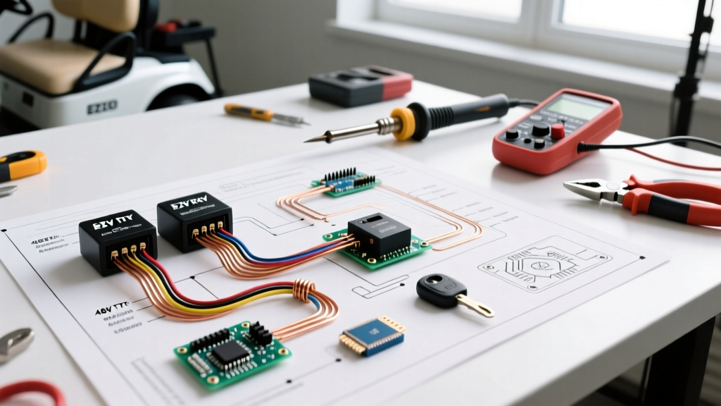
Before ordering replacement parts, use a digital multimeter to isolate the fault. Here are the most frequent edge cases we see in the repair shop:
- Voltage Sag Under Load (Bad SLA Cells): Your multimeter reads 25.8V at rest. You lift the rear wheel, apply the throttle, and the voltage drops to 21V. However, when the wheel touches the ground (under physical load), the voltage plummets to 16V, triggering the controller's Low Voltage Cutoff (LVC). Fix: Replace both 12V SLA batteries. Never replace just one cell in a series string.
- Melted Spade Connectors: The scooter cuts out after 5 minutes of riding. Inspect the B+ and M+ spade terminals on the controller. If the plastic housings are melted or discolored, high resistance has generated excessive heat. Fix: Cut back the oxidized wire, strip fresh copper, and crimp new high-temperature nickel-plated spades.
- Key Switch Failure: The key switch acts as a low-current relay trigger. If the dashboard lights up but the controller receives no B+ voltage, the internal contacts of the key cylinder have carbonized. Bypass the key switch temporarily with a jumper wire to confirm the diagnosis before sourcing a replacement 3-pin keyed ignition ($12-$15 in 2026).
Advanced Modification: The 36V Lithium-Ion Upgrade
Many enthusiasts use the E300 chassis as a donor for a lightweight lithium build. Upgrading from 24V SLA to a 36V (10S) Li-ion pack drastically reduces weight and increases range. However, this requires specific wiring alterations.
The Over-Voltage Problem: The stock Razor 24V controller features an Over-Voltage Protection (OVP) circuit set to roughly 31V. If you wire a fully charged 42V Li-ion pack to the stock controller, it will immediately trip the OVP and refuse to arm.
Required Wiring Changes for 36V
- Swap the Controller: Install a generic 36V 500W brushed DC controller (approx. $22 online). Wire the B+ and B- to the new battery's XT60 or XT90 discharge lead.
- Upgrade the Charger Port: The stock 24V charger port will fry if connected to a 42V Li-ion charger. Wire a dedicated 3-pin XLR charge port directly to the battery's BMS (Battery Management System) charge leads, completely bypassing the scooter's internal wiring harness for charging.
- Motor Compatibility: The stock 24V 250W motor can handle 36V for short bursts, but it will run hotter and the carbon brushes will wear 30% faster. For a permanent 36V build, swap the motor for a 36V 350W MY1016Z brushed motor and install a matching #25 chain sprocket.
Battery Safety and Compliance Standards
When modifying or repairing personal e-mobility devices, electrical safety is paramount. The transition from SLA to Lithium-ion introduces thermal runaway risks if the wiring is undersized or the BMS is inadequate. Ensure any custom battery packs comply with the UL 2272 Standard for Electrical Systems for Personal E-Mobility Devices, which mandates rigorous short-circuit and overcharge testing for the entire powertrain, not just the battery cells.
Furthermore, if you are retaining the stock SLA batteries, remember that AGM batteries release trace amounts of hydrogen gas during the absorption charging phase. As outlined in Battery University's guide on charging lead-acid batteries, always charge the scooter in a ventilated area and never seal the battery deck with airtight weather-stripping, which could trap combustible gases.
Summary of 2026 Replacement Costs
To help you budget your repair, here are the current average market prices for OEM-equivalent Razor E300/E100 wiring components:
- 24V 250W Speed Controller: $18 - $24
- 12V 9Ah SLA Battery (x2): $45 - $55 total
- Hall-Effect Throttle Assembly: $12 - $16
- Main Wiring Harness (with 30A fuse): $14 - $19
- 36V 10S3P Li-ion Upgrade Pack (12Ah): $110 - $140
By mastering the specific wiring pathways and utilizing precise multimeter diagnostics, you can reliably restore or upgrade your Razor scooter, ensuring years of safe, high-torque performance.