
Mastering the RV Electrical Panel Wiring PDF: A Vehicle-Specific Guide
When overhauling or troubleshooting the electrical system of a travel trailer, fifth wheel, or camper van, locating and understanding the correct electrical panel wiring PDF is your most critical first step. Unlike residential breaker boxes governed strictly by the National Electrical Code (NEC), recreational vehicle Power Distribution Centers (PDCs) must comply with specialized mobile standards, primarily NFPA 1192 (Standard on Recreational Vehicles) and the guidelines set forth by the Recreational Vehicle Industry Association (RVIA).
As of 2026, the rapid adoption of high-capacity lithium (LiFePO4) battery banks and 48V DC architectures in luxury rigs has made legacy wiring diagrams obsolete. This guide will teach you how to decode modern RV electrical panel schematics, identify critical failure modes, and safely execute panel upgrades using exact manufacturer specifications.
Anatomy of a Dual-Voltage RV Power Distribution Center
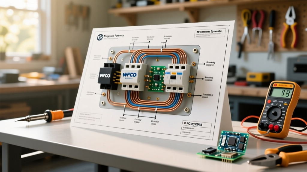
Most modern RVs utilize a combined AC/DC Power Distribution Center. If you download a wiring schematic for industry-standard units like the WFCO WF-8955-PEC (55-Amp) or the Progressive Dynamics PD4575 (75-Amp), you will notice the panel is physically and electrically divided into two distinct zones:
- 120V AC Section (Top): Fed by a 30A or 50A shore power cord or an integrated Automatic Transfer Switch (ATS) connected to an onboard generator. This section uses standard thermal-magnetic miniature circuit breakers (MCBs).
- 12V DC Section (Bottom): Fed by the onboard converter/charger and the house battery bank. This section utilizes automotive-style ATO/ATC blade fuses to protect low-voltage branch circuits (lights, water pumps, slide-out motors).
- The Converter/Charger Bridge: The internal or deck-mounted power converter steps down 120V AC to 13.6V DC to power the DC bus and charge the batteries. The wiring PDF will show heavy-gauge DC output wires (typically 4 AWG or 2 AWG) routing directly from the converter to the DC fuse bus and battery.
CRITICAL SAFETY WARNING: In a vehicle environment, vibration is the enemy of electrical connections. While residential panels allow solid-core copper wire, NFPA 1192 and ABYC marine standards (often adopted by high-end camper builders) strictly mandate the use of stranded copper wire for all DC and AC routing to prevent metal fatigue and catastrophic arcing from road vibration.
Decoding Schematic Symbols in RV Wiring PDFs
Reading an RV-specific electrical panel wiring PDF requires familiarity with mobile-specific symbols that do not appear in residential blueprints.
1. The Automatic Transfer Switch (ATS) Relay
In 50A RV schematics, you will frequently see an ATS block diagram situated between the shore power inlet and the main AC panel. The PDF will illustrate a time-delay relay (usually set to 30-60 seconds) that prioritizes generator power over shore power. If your AC panel loses power when switching sources, the PDF will guide you to test the ATS control board rather than the main breakers.
2. DC Grounding and Chassis Bonding
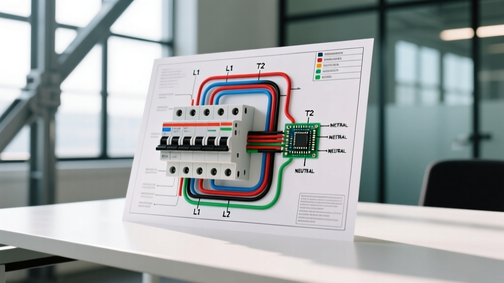
A common point of confusion in RV schematics is the grounding scheme. According to mobile electrical codes, the AC grounding conductor (green/bare) and the DC negative bus (white/black) are bonded together at one single point—usually the metal chassis of the power converter or the main PDC enclosure. The wiring PDF will show this bond via a specific grounding symbol connecting the DC negative bus to the chassis ground lug. Never bond neutral to ground at the shore power inlet or subpanels in an RV.
Wire Gauge and Routing Specifications for 12V DC Systems
When using your electrical panel wiring PDF to route new circuits from the DC fuse block to appliances, voltage drop is your primary constraint. A 12V system is highly sensitive to resistance. The RVIA recommends a maximum voltage drop of 3% for critical loads and 10% for general lighting.
| Wire Gauge (AWG) | Max Ampacity (Engine Bay) | Max Ampacity (Cabin) | Max Run for 3% Drop @ 12V (10A Load) | Common RV Application |
|---|---|---|---|---|
| 14 AWG | 15A | 20A | 7.5 ft (15 ft round trip) | LED Lighting, USB Receptacles |
| 12 AWG | 20A | 25A | 12 ft (24 ft round trip) | 12V Water Pump, Vent Fans |
| 10 AWG | 30A | 40A | 19 ft (38 ft round trip) | Slide-out Motors, 12V Fridges |
| 6 AWG | 60A | 80A | 38 ft (76 ft round trip) | Inverter DC Feed, Solar Charge Controller |
| 2/0 AWG | 195A | 200A+ | N/A (Main Trunk) | Main Battery to PDC Bus / Inverter |
Note: Always use UL 1426 (marine-grade) or SAE J1128 stranded copper wire with high-temperature insulation for RV applications. Standard THHN building wire is prohibited for 12V DC mobile use due to its rigid stranding and lower vibration tolerance.
Upgrading to Lithium: Modifying the Panel Schematic
If you are upgrading from lead-acid to lithium iron phosphate (LiFePO4) batteries, your original electrical panel wiring PDF must be mentally (and physically) updated. Standard WFCO or Progressive Dynamics converters output a fixed 13.6V, which will trigger a lithium Battery Management System (BMS) over-voltage fault and fail to fully charge the cells.
Required Schematic Modifications for LiFePO4:
- Converter Replacement: Swap the standard converter for a lithium-profile model (e.g., WFCO WF-8955LAD) that outputs a steady 14.6V.
- Class T Fuse Addition: The OEM PDF will likely show a standard ANL fuse on the main battery positive. For lithium banks capable of dumping 300A+ in a short circuit, you must update the schematic to include a Class T fuse (rated for 10,000 AIC) installed within 18 inches of the battery positive terminal.
- Heavy-Duty DC Bus Upgrade: Standard 30A blade fuses and 10 AWG bus bars may melt under the sustained high-amperage draw of a 3000W inverter pulling from lithium. Upgrade the main DC bus to a 250A rated copper block with 2/0 AWG feeders.
Real-World Troubleshooting Matrix
Use this matrix in conjunction with your specific rig's electrical panel wiring PDF to diagnose common mobile electrical failures.
| Symptom | PDF Section to Inspect | Common Culprit in RVs | Actionable Solution |
|---|---|---|---|
| 12V lights flicker when water pump kicks on | DC Converter Output & Main Battery Feed | Undersized converter wiring or corroded chassis ground bond. | Check voltage at the DC bus under load. If it drops below 11.5V, upgrade converter-to-bus wiring to 4 AWG and clean the chassis ground lug. |
| Shore power works, but generator does not power AC panel | Automatic Transfer Switch (ATS) Control Board | Failed ATS time-delay relay or loose 120V AC neutral on the generator input side. | Use a multimeter to verify 120V at the ATS generator input terminals. If present, replace the ATS unit (e.g., Iota ITS-50R). |
| DC blade fuses repeatedly blow without a short circuit | DC Branch Circuit Routing | Vibration-induced chafing where wire passes through bulkheads without grommets, or loose spade connectors creating high resistance/heat. | Inspect all bulkhead pass-throughs. Replace push-on spade connectors with ring terminals and apply dielectric grease. |
| Battery charges to only 70% capacity | Converter AC Input & DC Output | OEM converter lacks lithium charging profile, or voltage drop across the DC bus is tricking the converter into early float mode. |
Final Best Practices for Mobile Electrical Work
Always print your electrical panel wiring PDF and keep it in the rig's physical documentation binder. When modifying the system, use a red pen to mark changes directly on the paper schematic. In the event of a roadside electrical failure at night, having a marked-up, physical PDF is infinitely more reliable than trying to download a schematic on a tablet with zero cell service. Remember to torque all AC and DC terminal lugs to the manufacturer's exact inch-pound specifications using an insulated torque screwdriver, as thermal expansion and road vibration will quickly loosen hand-tightened connections.