
The Hidden Risks of Free Electrical Wiring Diagram Software in Code Compliance
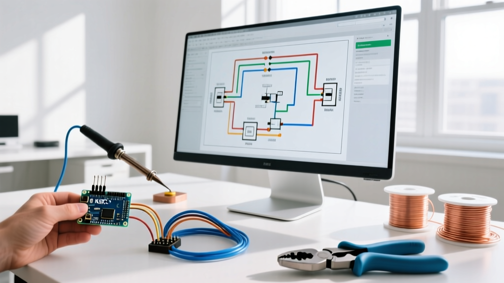
For DIY enthusiasts, students, and even some budget-conscious contractors, the allure of free electrical wiring diagram software is undeniable. Tools like QElectroTech, TinyCAD, and Dia offer a zero-cost entry point into schematic design. However, when transitioning from hobbyist breadboarding to hardwired, high-voltage installations, the stakes change dramatically. Electrical documentation is not just about drawing lines; it is a legal and safety-critical record that must adhere to strict regulatory frameworks.
The National Electrical Code (NEC) does not explicitly mandate a specific brand of CAD software, but it does enforce rigorous standards for identification, labeling, and mechanical execution of work. Under NEC Article 110.12, installations must reflect 'neat and workmanlike' execution. Inspectors increasingly interpret this to include the clarity, standardization, and accuracy of the submitted wiring diagrams. Using free software that relies on outdated or non-standardized symbol libraries can lead to misinterpretations in the field, resulting in failed inspections, voided equipment warranties, or catastrophic safety failures.
Evaluating Top Free Tools for NEC and IEC Symbol Accuracy
Not all free electrical wiring diagram software is created equal. The primary differentiator between a professional Electrical CAD (ECAD) suite and a free alternative is the built-in component library. Professional tools automatically update to reflect IEEE 315 (US standard) and IEC 60617 (International standard) symbol changes, whereas free tools often require manual library management.
| Software | IEEE 315 / NEC Library | IEC 60617 Library | DWG/DXF Export | Best Use Case |
|---|---|---|---|---|
| QElectroTech | Partial (Manual) | Excellent | Yes (SVG/DXF) | Open-source industrial control panels |
| TinyCAD | Basic | Poor | No | Low-voltage DIY & hobbyist circuits |
| ProfiCAD (Free) | Good | Good | No (Paid only) | Quick residential wiring sketches |
| AutoCAD Electrical | Comprehensive | Comprehensive | Yes | Commercial/Industrial (Paid Baseline) |
QElectroTech: The Open-Source Contender
Of all the free electrical wiring diagram software options, QElectroTech is the most capable for serious, code-compliant work. Because it is open-source, the community has built extensive IEC 60617 libraries, making it highly suitable for motor control centers and PLC wiring. However, for US-based electricians adhering strictly to NEMA and IEEE 315 standards, the out-of-the-box experience can be frustrating. You will often need to manually import or draw standard US symbols for specific components like GFCI receptacles, AFCI breakers, and specific NEMA-rated motor starters. If you fail to update these symbols, a field technician might confuse a standard thermal overload relay with a magnetic motor starter, leading to improper wiring of the control circuit.
TinyCAD and Dia: Why Hobbyist Tools Fail Commercial Inspections
Tools like TinyCAD and Dia are essentially generic vector drawing programs with a few basic electrical stencils bolted on. They lack parametric data. In professional ECAD, a symbol for a 40A double-pole breaker carries metadata (manufacturer, trip curve, interrupting capacity). In TinyCAD, it is just a collection of lines. If an inspector asks for a bill of materials (BOM) or a short-circuit current calculation based on your diagram, free generic tools cannot generate this data. Relying on them for commercial panel schedules is a direct path to a rejected permit.
Real-World Failure Modes: When Generic Symbols Cause Hazards
To understand the safety implications of using inadequate free electrical wiring diagram software, consider a real-world edge case involving Variable Frequency Drive (VFD) installations. A technician used a generic free drawing tool to map out a 480V, 15HP VFD control circuit. Instead of using the standardized IEEE 315 symbol for an isolated ground (IG) receptacle, they used a standard chassis ground symbol due to software limitations.
The installing electrician followed the diagram literally, bonding the VFD's sensitive logic ground to the main equipment grounding conductor rather than running an isolated ground back to the panel. The result? Severe electromagnetic interference (EMI) caused the VFD to misread the motor encoder feedback, leading to a runaway over-speed condition that destroyed the mechanical coupling. The root cause was traced back to the schematic's non-standard symbol. According to OSHA Electrical Safety Standards, accurate documentation is a foundational element of workplace electrical safety and lockout/tagout (LOTO) procedures. Ambiguous diagrams directly violate the spirit of safe work practices.
Code Insight: NEC Article 408.4 requires that every circuit in a switchboard or panelboard be legibly identified as to its purpose. If your free software cannot generate clear, standardized panel schedules that link directly to your schematic pages, you are already in violation before the first wire is pulled.
NFPA 70E and the Arc Flash Documentation Gap
Safety and code compliance extend beyond the NEC into NFPA 70E (Standard for Electrical Safety in the Workplace). NFPA 70E requires equipment like switchboards and motor control centers to be field-marked with arc flash warning labels, which must include the incident energy level and arc flash boundary. Calculating these values requires precise data regarding the upstream breaker's clearing time and the available fault current.
Paid enterprise software (like SKM Power*Tools or ETAP, which cost thousands of dollars annually) integrates directly with wiring diagrams to run these fault studies. Free electrical wiring diagram software has zero capability to perform arc flash calculations. If you are designing a commercial facility in 2026, using free software means you must manually export your circuit parameters into a separate spreadsheet or third-party calculator to generate your arc flash labels. This manual transcription introduces a high risk of human error, potentially resulting in an undersized PPE recommendation for maintenance workers.
The Code Compliance Checklist for Open-Source Schematics
If you must use free electrical wiring diagram software due to budget constraints, you must implement a rigorous manual review process to ensure your drawings meet safety and code standards. Use this checklist before submitting your plans for permitting:
- Verify Symbol Standards: Ensure all symbols strictly adhere to IEEE 315 (for US projects) or IEC 60617 (for international projects). Do not mix standards on the same page.
- Include Wire Gauge and Type Callouts: Every line representing a conductor must be labeled with its exact specification (e.g., '3/C #12 AWG THHN/THWN'). Free software rarely automates this; you must add it manually.
- Define Grounding Topology: Clearly differentiate between equipment grounding conductors (EGC), grounded conductors (neutral), and isolated grounds using distinct colors and standardized symbols per NEC Article 250.
- Provide a Complete Bill of Materials (BOM): Include manufacturer, model number, and UL/CSA listing status for every component. Inspectors will cross-reference your BOM with the physical equipment on site.
- Add Terminal Block Numbers: For control panels, ensure every wire termination point is assigned a unique terminal block number that matches the physical layout of the panel.
When to Upgrade to Paid Electrical CAD
While free electrical wiring diagram software is excellent for learning, prototyping, and simple residential additions, there is a definitive tipping point where upgrading is mandatory for safety and compliance. You should transition to a paid ECAD solution (such as AutoCAD Electrical, EPLAN, or SolidWorks Electrical) when:
- Your project involves 3-phase power over 208V.
- You are designing PLC-based automation systems requiring I/O mapping and terminal strip layouts.
- The local Authority Having Jurisdiction (AHJ) requires digital DWG submissions with embedded metadata for facility management systems.
- You need to generate automated wire routing and harness length calculations for custom control enclosures.
In 2026, a commercial license for AutoCAD Electrical averages around $1,975 per year. While this is a significant investment compared to free tools, the cost of a single failed commercial inspection, a miswired 480V panel, or an OSHA citation for improper LOTO documentation will vastly exceed the price of professional software.
Frequently Asked Questions (FAQ)
Can I use free electrical wiring diagram software for a residential permit?
Yes, for simple residential projects like adding a subpanel or wiring a detached garage, free tools like ProfiCAD or QElectroTech are generally acceptable. However, your drawings must still include standard NEC symbols, load calculations, and clear wire gauge callouts to pass the local building inspector's review.
Do free tools support NEC 2023 and 2026 code updates?
Unlike paid software that pushes automatic updates when the NEC cycle revises requirements (such as new GFCI/AFCI mandates or updated grounding rules), free software relies on community updates. You are responsible for manually verifying that your component libraries and design practices reflect the most current code cycle adopted by your state.
Is it safe to use generic drawing tools like MS Visio for electrical schematics?
While MS Visio has basic electrical stencils, it is not a true ECAD program. It lacks electrical rule checking (ERC), which automatically flags critical errors like shorted power rails, ungrounded neutral points, or mismatched pin connections. Relying on Visio for complex control wiring introduces a high risk of undetected design flaws.