
The Anatomy of a Travel Trailer Electrical System
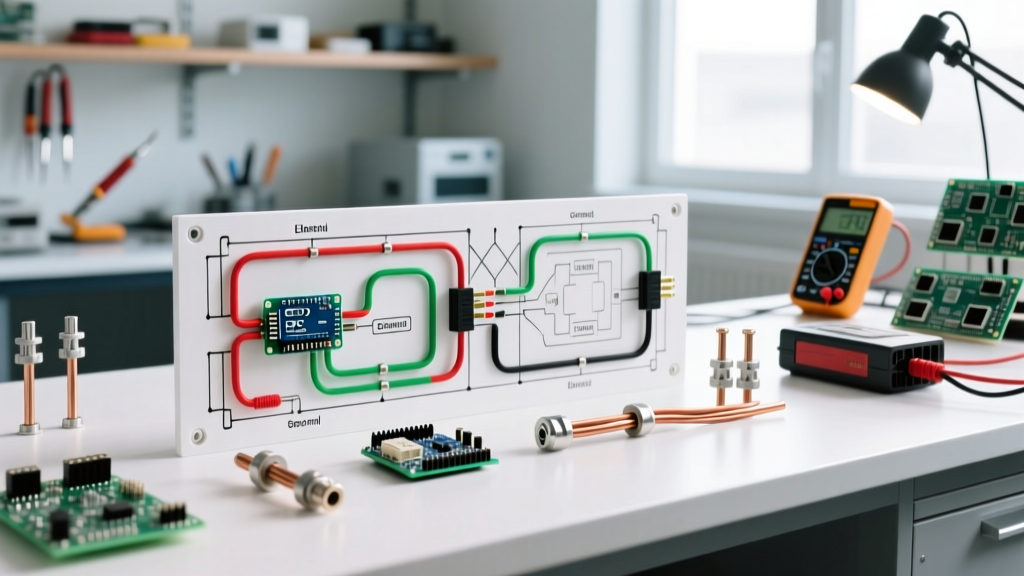
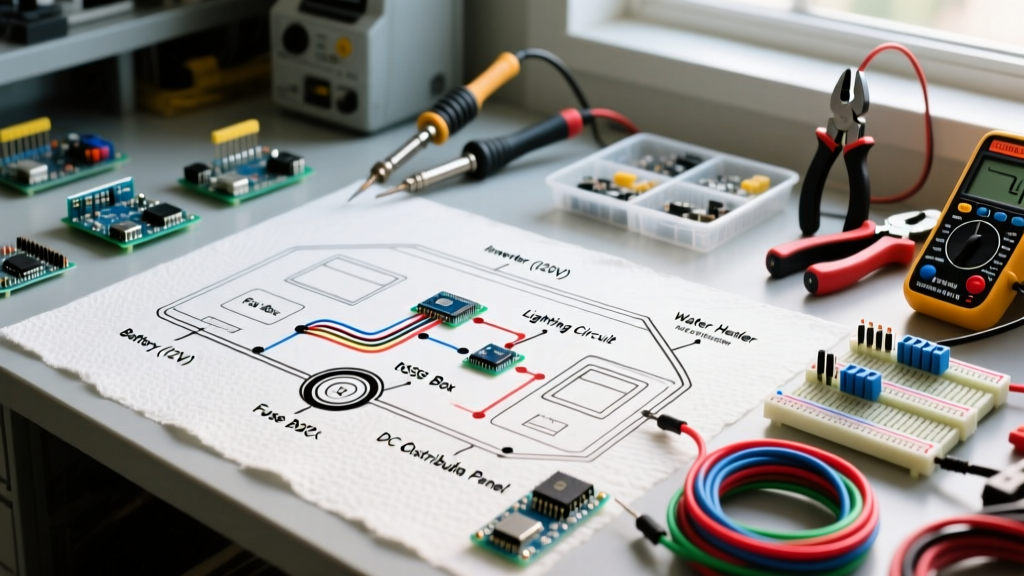
Wiring a travel trailer is fundamentally different from residential electrical work. Unlike a standard home that relies solely on 120V AC grid power, a travel trailer operates on a split-bus architecture. You are managing two entirely distinct systems: a 120V AC shore power system for heavy appliances, and a 12V DC system for lighting, water pumps, and control boards. According to the National Electrical Code (NEC) Article 551, these systems must be meticulously isolated, properly grounded, and protected by dedicated overcurrent devices. As of 2026, modern travel trailers also increasingly integrate lithium-iron-phosphate (LiFePO4) battery banks and smart DC-DC chargers, making a precise wiring diagram for travel trailer applications more critical than ever.
Core Components of the RV Power Center
The heart of your travel trailer's electrical system is the Power Center (often called a converter/breaker panel). This single unit houses the 120V AC circuit breakers, the 12V DC blade fuses, and the AC-to-DC converter. For a standard 30-amp travel trailer, the WFCO WF-8955PEC (55-Amp) or the Progressive Dynamics PD4655V are the industry benchmarks, typically retailing between $280 and $320 in early 2026. These units feature a 'deck-mounted' design, allowing you to wire the AC and DC branches directly into the rear knockouts.
Step-by-Step Walkthrough: 120V AC Shore Power Wiring
The 120V AC system brings power from the campground pedestal through your 30A or 50A shore cord, into the main breaker, and out to branch circuits (outlets, microwave, air conditioner).
Step 1: Shore Cord to Main Breaker
- Route the Cord: Feed your 30A (10/3 AWG stranded) or 50A (6/3 AWG stranded) RV power cord through the designated exterior strain-relief gland. Never use solid-core residential Romex; the vibration of travel will fracture solid copper over time.
- Terminate the Ground: Connect the bare copper ground wire to the power center's main ground bus bar. Torque to 35 in-lbs.
- Connect Neutral and Hot: Route the white (neutral) to the neutral bus bar, and the black (hot) directly to the main 30A double-pole breaker. Ensure no stray wire strands are protruding, which is a leading cause of RV electrical fires.
Step 2: Branch Circuit Wiring & GFCI Protection
From the main breaker, wire your 15A and 20A branch breakers. Use 14/2 AWG stranded wire for 15A lighting/outlet circuits, and 12/2 AWG for 20A kitchen/bathroom circuits. Per NEC Article 551, GFCI protection is mandatory for any receptacle within 6 feet of a sink, in the bathroom, or on the exterior. Instead of buying expensive GFCI breakers, wire a standard 15A breaker to a GFCI receptacle as the first device in the daisy chain, protecting all downstream outlets.
Step-by-Step Walkthrough: 12V DC Battery & Fuse Wiring
The 12V DC system is where most DIY mistakes occur, primarily due to confusing automotive wiring standards with RVIA (Recreation Vehicle Industry Association) standards.
⚠️ CRITICAL RVIA COLOR CODE WARNING:In standard automotive wiring, Red is positive and Black is ground. In RVIA 12V DC wiring, this is reversed. According to RVIA standards, White is Negative (Ground) and Black is Positive (+12V). Wiring a 12V appliance using automotive color logic in an RV will instantly fry the appliance's control board and blow your DC fuses.
Step 1: Battery to Disconnect and Power Center
- Heavy Gauge Feed: Run 6 AWG stranded copper wire from the positive terminal of your deep-cycle or LiFePO4 battery bank to a 150A inline ANL fuse, then to a heavy-duty battery disconnect switch.
- Converter Connection: From the disconnect, route the 6 AWG black (positive) wire to the 12V positive bus bar on your WFCO or Progressive Dynamics power center. Connect the 6 AWG white (negative) wire to the negative bus bar.
- Chassis Ground: Bond the negative bus bar to the trailer's steel chassis using a minimum 8 AWG wire and a star washer to bite through the paint, ensuring a clean metal-to-metal connection.
Step 2: 12V Branch Circuits and Crimping
Wire your 12V lights, water pump, and fans to the blade fuse block. Use 14 AWG wire for circuits up to 10A, and 12 AWG for circuits up to 15A (like the water pump or slide-out motors). Expert Tip: Never use cheap stamped-metal crimpers. Invest in a ratcheting crimper (like the Titan 11177 or Knoweasy equivalent, ~$35) and use adhesive-lined marine-grade heat shrink terminals. The adhesive melts and seals the connection against the high humidity and condensation inherent in travel trailers.
Wire Gauge, Breaker Sizing, and Voltage Drop Matrix
Voltage drop is the silent killer of 12V RV systems. A 12V water pump requires at least 10.5V to operate its internal pressure switch. If your wire is too thin or the run is too long, voltage drops below the threshold, causing the pump to chatter or the converter to overwork. Use the matrix below to size your 12V DC branches correctly for a maximum 3% voltage drop.
| 12V Appliance / Circuit | Max Draw | Wire Gauge (Under 10 ft) | Wire Gauge (10-20 ft) | Fuse Size |
|---|---|---|---|---|
| LED Interior Lighting | 2A - 4A | 16 AWG | 14 AWG | 5A Blade |
| 12V Water Pump (e.g., Shurflo 4008) | 7A - 10A | 14 AWG | 12 AWG | 15A Blade |
| Slide-Out Motor / Awning | 15A - 25A | 10 AWG | 8 AWG | 30A Auto Reset |
| 12V Compressor Fridge (e.g., Furrion) | 8A - 12A | 12 AWG | 10 AWG | 15A Blade |
Integrating the 7-Way RV Bargman Plug
Your travel trailer's wiring diagram must also account for the 7-way tow vehicle connector. This plug powers your trailer brakes, running lights, and provides a trickle charge from the tow vehicle's alternator. The standard pinout is:
- Pin 1 (Brown): Tail and Running Lights
- Pin 2 (Blue): Electric Trailer Brakes (Requires 10 AWG wire back to the breakaway switch and axles)
- Pin 3 (White): 12V Negative / Ground (Must be bonded to the trailer tongue)
- Pin 4 (Green): Right Turn / Stop
- Pin 5 (Red): 12V Auxiliary / Battery Charge (Connect to battery positive via a 40A auto-reset breaker)
- Pin 6 (Yellow): Left Turn / Stop
- Pin 7 (Black/Center): Backup Lights / Aux
Common Failure Modes & Troubleshooting Edge Cases
The 'Chattering' Converter Symptom: If your power center's cooling fan cycles on and off rapidly, or you hear a buzzing from the 12V fuses, you likely have a high-resistance ground. Check the main white negative wire where it bolts to the chassis. Remove the bolt, sand the frame to bare metal, apply dielectric grease, and re-torque. Stray resistance forces the converter to work harder, generating excess heat.
Galvanic Corrosion at the Battery Terminals
Travel trailers are exposed to extreme temperature swings and road salt. Using dissimilar metals (like copper wire lugs directly on lead-acid posts without proper treatment) leads to galvanic corrosion, which increases resistance and causes severe voltage drop. Always use tinned copper lugs and coat the final connection with a dedicated battery terminal protector spray or No-Ox-Id A-Special grease.
Lithium Battery Converter Incompatibility
If you are upgrading from lead-acid to LiFePO4 batteries in 2026, your older WFCO or Progressive Dynamics converter's 'desulfation mode' (which spikes voltage to 14.4V+ periodically) will trigger the Battery Management System (BMS) to shut down the battery to protect it. You must either flip the DIP switch on newer WFCO units to 'Lithium Mode' or replace the deck with a dedicated lithium charge profile module (like the Progressive Dynamics PD4655LIV). For more technical bulletins on RV power conversions, refer to the Progressive Dynamics support documentation.
Final Inspection and Energization
Before plugging into shore power or connecting the 12V battery, perform a continuity test. Use a digital multimeter to verify there is zero continuity (infinite resistance) between the 120V Hot bus and the Ground bus. A short here will result in an immediate, explosive trip of the campground pedestal breaker. Once verified, connect the 12V battery first to energize the control boards, then plug in your 30A shore cord. Measure the voltage at the furthest 120V outlet and the furthest 12V light fixture to ensure your wiring diagram for travel trailer execution is operating within safe, efficient parameters.