
The Critical Foundation of Home Power: Electrical Breaker Box Wiring
Proper electrical breaker box wiring is the central nervous system of any residential or commercial building. A poorly wired panel doesn't just cause nuisance tripping; it creates severe arc-flash hazards, degrades equipment lifespan, and violates National Electrical Code (NEC) mandates. As of 2026, with the widespread adoption of the 2023 NEC and early 2026 local amendments, the tolerances for panel wiring errors have shrunk to zero. Inspectors are now strictly enforcing torque specifications and AFCI/GFCI expansions.
This guide bypasses generic advice and dives directly into the technical specifications, wiring diagrams, and failure modes associated with modern load centers like the Square D Homeline 200A (Model HOM2040M200PC) and Eaton BR series. Whether you are an apprentice electrician or a seasoned DIYer verifying your subpanel layout, understanding the exact physics and code requirements of panel wiring is non-negotiable.
⚠️ SAFETY WARNING: Working inside an energized breaker box exposes you to lethal voltage. The main service lugs remain energized even when the main breaker is switched OFF. Always use a Category III or IV multimeter (such as the Fluke 117) to verify zero energy before touching internal bus bars. According to the U.S. Consumer Product Safety Commission (CPSC), electrical fires account for over 50,000 home fires annually, many originating from loose panel connections.
Anatomy of a Modern Load Center
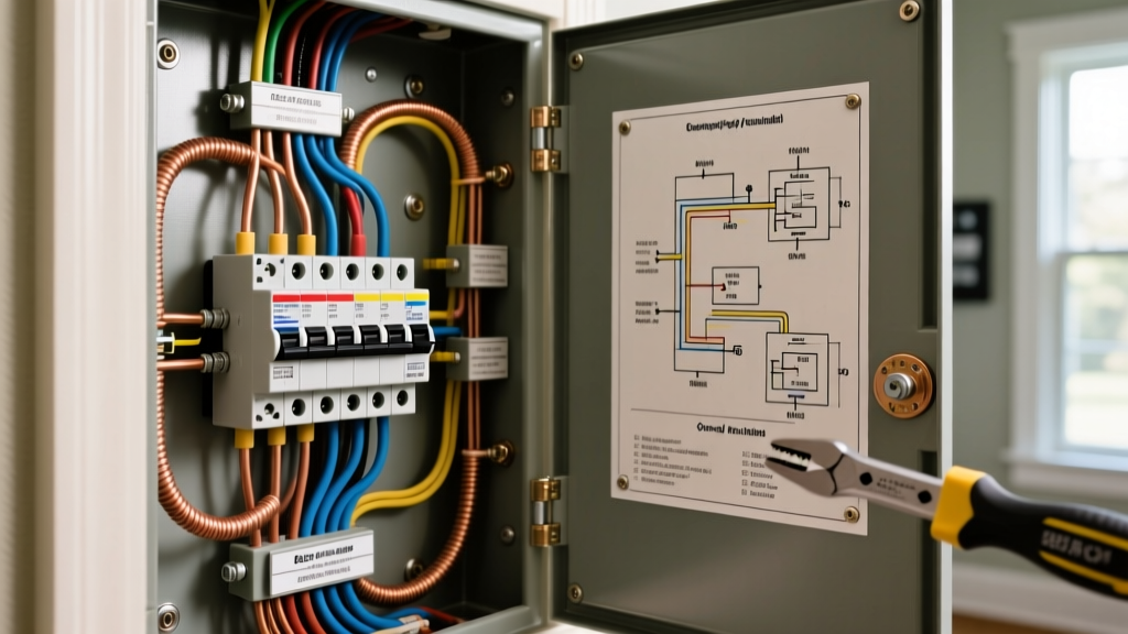
Before executing any electrical breaker box wiring, you must understand the internal architecture of the panel. A standard 200-amp main breaker panel contains four critical termination zones:
- Main Service Lugs: Where the utility's 2/0 AWG aluminum or copper service entrance conductors terminate. These are always live.
- Hot Bus Bars: Two parallel aluminum or copper bars that distribute 120V each (240V across both). They are staggered to allow double-pole breakers to straddle both phases.
- Neutral Bus Bar: A silver-plated or aluminum bar with multiple termination screws. In a main panel, this is physically bonded to the enclosure.
- Ground Bus Bar: Often a separate green-painted or bare aluminum bar. In a main panel, it is bonded to the neutral bar via the main bonding jumper (a green screw or copper strap).
Wiring Flow: Main Panel vs. Subpanel
The most common code violation in residential electrical breaker box wiring is failing to separate the neutral and ground in a subpanel. The NEC is explicit about this distinction under Article 250.
Comparison Matrix: Main Panel vs. Subpanel Wiring
| Wiring Parameter | Main Service Panel | Downstream Subpanel |
|---|---|---|
| Neutral-to-Ground Bond | Bonded (Main bonding jumper installed) | Separated (Bonding screw/strap removed) |
| Neutral Bar Termination | Current-carrying and grounded | Strictly current-carrying (isolated from enclosure) |
| Ground Bar Termination | Safety ground only | Safety ground only (connected to enclosure) |
| Feeder Cable Requirement | N/A (Utility feed) | 4-wire (2 Hots, 1 Neutral, 1 Ground) |
| NEC Reference | NEC 250.24(A)(5) | NEC 250.32(B)(1) |
If you wire a subpanel like a main panel (bonding the neutral to the ground), normal neutral return current will flow on the bare copper ground wire and the metal conduit. This creates a parallel neutral path, which can electrify metal plumbing, appliance chassis, and cause lethal shock hazards.
Wire Gauge & Ampacity Sizing Guide
Selecting the correct wire gauge for your breakers is dictated by NEC Article 310. The table below outlines standard residential copper and aluminum sizing for THHN/THWN-2 conductors in a 90°C rating, but terminated at the standard 75°C rating of most modern breakers.
| Breaker Size (Amps) | Copper Wire (AWG) | Aluminum Wire (AWG) | Max Continuous Load (80%) |
|---|---|---|---|
| 15A | 14 AWG | 12 AWG | 12 Amps |
| 20A | 12 AWG | 10 AWG | 16 Amps |
| 30A | 10 AWG | 8 AWG | 24 Amps |
| 40A | 8 AWG | 6 AWG | 32 Amps |
| 50A | 6 AWG | 4 AWG | 40 Amps |
| 60A | 4 AWG | 3 AWG | 48 Amps |
| 100A | 3 AWG | 1 AWG | 80 Amps |
| 200A (Main) | 2/0 AWG | 4/0 AWG | 160 Amps |
Critical NEC Rules for Panel Wiring (2026 Perspective)
The National Fire Protection Association (NFPA 70) has tightened regulations surrounding panel terminations. Ignoring these will result in an immediate failed inspection.
1. Mandatory Torque Specifications (NEC 110.14(D))
Since the 2017 NEC cycle, and heavily enforced in 2026, electricians must use a calibrated torque screwdriver to tighten breaker and bus bar lugs. Hand-tightening is no longer acceptable. For example, a standard Square D QO 15A-20A breaker requires exactly 35 inch-pounds of torque on the lug screw. Over-torquing strips the aluminum threads or snaps the screw; under-torquing causes thermal expansion and contraction, leading to arcing and melted bus bars. A tool like the CDI 1002MFRMH (10-50 in-lb range) is a mandatory investment.
2. The 'Double-Tapping' Rule
Connecting two wires under a single breaker lug is a violation unless the breaker is explicitly listed and marked for two conductors. Many Square D QO breakers (15A-30A) feature a saddle-style lug with a groove designed to accept two identically sized wires. However, Eaton BR and Siemens QT breakers generally do not allow double-tapping. If you need to pigtail two circuits, use a wire nut in the panel gutter and run a single pigtail to the breaker.
3. AFCI and GFCI Expansion
Under NEC 210.12 and 210.8, nearly every 120V, 15A and 20A branch circuit in a dwelling must now feature Arc-Fault Circuit Interrupter (AFCI) or Dual-Function (AFCI/GFCI) protection. When wiring these breakers, the circuit's neutral wire must terminate directly on the breaker's neutral pigtail or screw, not on the panel's neutral bus bar. The breaker's coiled white pigtail is the only wire that connects to the neutral bar. Bypassing this sequence renders the AFCI logic board useless.
Step-by-Step: Wiring a 240V Double-Pole Breaker
Wiring a 240V circuit (e.g., for an EV charger, HVAC condenser, or electric range) requires straddling both hot bus bars. Here is the exact sequence for a 50A EV charger circuit using 6 AWG copper THHN.
- Prepare the Conductors: Strip exactly 3/8 inch of insulation from the black and red hot wires. Do not nick the copper strands; nicked wires create localized hot spots under high continuous loads.
- Seat the Breaker: Align the 50A double-pole breaker over the stabs on the bus bar. Press down firmly and evenly on both sides until it snaps into the retaining clip. Ensure the bus bar stab is fully inserted into the breaker's jaw.
- Terminate the Hots: Insert the stripped black and red wires into the breaker lugs. Using your calibrated torque screwdriver set to the manufacturer's spec (typically 40-45 in-lbs for 50A), tighten the set screws until the tool clicks.
- Route the Ground: Terminate the bare copper or green ground wire onto the panel's ground bus bar. Torque to the bus bar manufacturer's specification (usually 35 in-lbs).
- Verify the Gutter: Ensure no bare copper is exposed outside the breaker lug and that the wire insulation is not pinched under the screw head. The insulation should sit flush against the plastic housing of the breaker.
Common Failure Modes & Troubleshooting
Even with perfect electrical breaker box wiring, environmental factors and time can introduce faults. Here are the most common failure modes encountered in the field:
- Thermal Creep (Loose Neutrals): Aluminum bus bars expand and contract with temperature changes. Over 5 to 10 years, neutral screws can loosen. This increases resistance, generating heat that melts the wire insulation. Fix: Annual infrared thermography scans or manual torque checks during off-peak hours.
- Bus Bar Corrosion: In coastal or high-humidity environments, aluminum bus bars can oxidize, creating a high-resistance layer. Fix: Use panels with tin-plated copper bus bars (like the Siemens Ultimate series) in corrosive environments.
- Harmonic Overheating: Modern homes with massive amounts of LED drivers, solar inverters, and variable-frequency drives (VFDs) generate triplen harmonics. These harmonics stack on the neutral bus bar, causing it to overheat even if the hot legs are under capacity. Fix: Oversize the neutral bus bar or use K-rated transformers for dedicated subpanels.
Frequently Asked Questions (FAQ)
Can I wire my own electrical breaker box?
Legally, this depends on your local municipality. Many jurisdictions allow homeowners to pull permits and wire their own primary residence, provided they pass rough-in and final inspections. However, utility companies often require a licensed master electrician to pull the meter and make the final service entrance connections. Always check with your local Authority Having Jurisdiction (AHJ) before starting.
Why is my breaker box making a buzzing sound?
A faint hum is normal due to the alternating magnetic fields inside the breakers. However, a loud, aggressive buzzing or crackling sound indicates a loose connection, a failing breaker jaw, or an overloaded bus bar. This is an immediate fire hazard. Shut off the main breaker and contact a licensed electrician to perform a thermal scan and torque check.
What is the required working space around a panel?
According to OSHA standard 1910.303 and NEC 110.26, you must maintain a clear working space in front of the panel. This space must be at least 30 inches wide (or the width of the equipment, whichever is greater), 36 inches deep, and 6.5 feet high. You cannot store boxes, shelving, or appliances in this zone.
Final Thoughts on Panel Integrity
Electrical breaker box wiring is not an area for shortcuts or approximations. The cost of a 200A load center might only be $200 to $300 in 2026, and individual AFCI breakers average around $45 each, but the cost of a panel fire exceeds hundreds of thousands of dollars. By adhering strictly to torque specifications, respecting the neutral-ground bond rules, and utilizing proper wire gauges, you ensure a safe, code-compliant, and future-proof electrical distribution system.