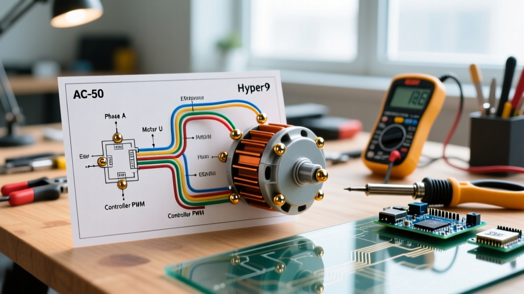

The Reality of Vehicle-Specific Electric Motor Wiring
Wiring an electric motor for a vehicle is fundamentally different from wiring an industrial motor for a stationary conveyor belt. When enthusiasts and professional shops search for electric motor wiring diagrams, they often encounter generic 3-phase AC induction schematics designed for grid-tied variable frequency drives (VFDs). However, vehicle traction motors operate in a harsh, high-vibration environment requiring 4-quadrant operation (motoring and regenerative braking in both forward and reverse), rapid transient response, and strict mobile safety interlocks.
As of 2026, the aftermarket EV conversion industry has largely standardized around liquid-cooled AC induction and interior permanent magnet (IPM) motors paired with Silicon Carbide (SiC) inverters. These systems demand meticulous attention to high-voltage (HV) phase routing, low-voltage (LV) logic isolation, and electromagnetic interference (EMI) shielding. According to the U.S. Department of Energy Alternative Fuels Data Center, the integration of the power electronics and motor assembly is the most critical failure point in custom electric vehicle architectures.
Anatomy of a Traction Motor Wiring Harness
A complete vehicle traction motor wiring harness is divided into three distinct subsystems. Mixing these subsystems or failing to isolate them is the primary cause of erratic throttle behavior and inverter fault codes.
- High-Voltage (HV) Power Phase Cables: The thick conductors carrying DC bus voltage to the inverter, and the 3-phase AC waveforms from the inverter to the motor stator.
- Low-Voltage (LV) Logic and Sensor Harnesses: The 12V or 5V signals handling throttle inputs, direction selection, temperature sensors, and resolver/encoder feedback.
- Safety and Interlock Circuits: The High Voltage Interlock Loop (HVIL), inertia switches, and manual service disconnects (MSDs) that ensure the HV bus is de-energized during a collision or maintenance event.
Case Study 1: HPEVS AC-50 (Light EV & Golf Cart Conversions)
The HPEVS (Electric Vehicles of America) AC-50 is a staple in lightweight EV swaps, neighborhood electric vehicles (NEVs), and golf carts. It operates on a 72V nominal DC bus and is typically paired with a Curtis 1238-7601 inverter.
Phase Wiring and Commutation Logic
The AC-50 utilizes a 3-phase U, V, W connection. A common mistake when interpreting standard electric motor wiring diagrams is attempting to reverse the motor's direction by swapping two of the phase wires (e.g., swapping U and V). In an industrial setup, this reverses the rotating magnetic field. In a vehicle EV setup, swapping phase wires will cause the Curtis inverter to throw a 'Motor Phase Sequence' fault because the inverter's internal logic expects a specific phase alignment correlated with the motor's rotor position sensor.
Expert Rule: Never reverse an EV traction motor by swapping HV phase cables. Direction control must be handled exclusively via the inverter's 12V logic inputs (Forward/Reverse switch) mapped to the gear selector.
Thermistor Wiring
The AC-50 stator embeds a 10k Ohm NTC thermistor. This must be wired back to the Curtis controller's analog input using 18 AWG shielded twisted pair (STP) cable. If unshielded wire is used, the high dV/dt (voltage over time) switching spikes from the SiC or IGBT inverter modules will induce noise in the thermistor circuit, causing the controller to falsely read the motor at 150°C and derate power to zero.
Case Study 2: NetGain Hyper9 (Classic Car & Truck EV Swaps)
For heavier vehicles like classic muscle cars, pickup trucks, and off-road rigs, the NetGain Hyper9 (specifically the HG4001 or HG4002 models) is the industry standard. It operates on a 100V to 130V DC bus, pushing up to 300 peak amps through the SME ACX inverter.
The High Voltage Interlock Loop (HVIL)
Unlike low-voltage golf cart systems, the Hyper9 operates at voltages lethal to humans. Therefore, the wiring diagram must incorporate a 12V HVIL. The HVIL is a series circuit that passes through the inverter cover, the manual service disconnect (MSD), and the inertia crash switch. If any of these physical connections are broken, the 12V signal drops, and the SME ACX inverter immediately disables the IGBT gates and actively discharges the DC bus capacitors through a bleeder resistor within milliseconds.
Resolver Signal Integrity
The Hyper9 uses a brushless resolver to track rotor position. The resolver wiring requires three twisted pairs: Excitation, Sine, and Cosine. These must be routed in a separate conduit or braided sleeve away from the HV phase cables. The shield must be grounded at the inverter end only (pigtail grounded to the chassis or logic ground) to prevent ground loops, which manifest as violent torque oscillations at low speeds.
Wire Gauge, Insulation, and Routing Matrix
Selecting the correct wire gauge and insulation type is critical. Standard THHN building wire is strictly prohibited in vehicle EV conversions due to its inability to withstand high-frequency inverter spikes and automotive fluids. Below is the specification matrix for 2026 aftermarket EV builds.
| System Voltage | Peak Current | Recommended AWG | Insulation Type | Bending Radius |
|---|---|---|---|---|
| 72V DC (AC-50) | 150A (10 sec) | 2 AWG | TXL or XLPE | 4x Cable OD |
| 100V-130V DC (Hyper9) | 300A (10 sec) | 1/0 AWG | XLPE (Inverter-Rated) | 5x Cable OD |
| 144V+ DC (Dual Motor) | 500A+ (10 sec) | 2/0 AWG or 3/0 AWG | Shielded XLPE | 6x Cable OD |
| Logic / Sensors | < 2A | 18 to 24 AWG | STP (Shielded Twisted Pair) | Standard |
Note: XLPE (Cross-Linked Polyethylene) is mandatory for the 3-phase AC cables between the inverter and the motor. The high-frequency PWM (Pulse Width Modulation) switching creates voltage reflections at the motor terminals that can exceed 2x the DC bus voltage. Standard PVC insulation will suffer corona discharge and melt, leading to a dead short to the motor casing.
Common Wiring Failure Modes in Mobile Applications
When troubleshooting EV conversions, 90% of electrical faults stem from improper termination and routing rather than component failure. Here are the most frequent edge cases:
1. Vibration-Induced Crimp Failures
Using standard indent crimpers on HV lugs creates stress concentrations that fracture under the constant harmonic vibration of a vehicle chassis. Solution: Use a hex-crimp or quad-point crimp die specifically sized for the wire and lug combination (e.g., TE Connectivity AMP or Greenlee hydraulic hex crimpers). Follow up with an adhesive-lined heat shrink tube rated for 125°C to seal out moisture and provide strain relief.
2. Inverter Grounding Loops
The inverter casing and the motor casing must be bonded to the vehicle chassis using a dedicated, braided copper grounding strap (minimum 4 AWG). If the motor relies on its mounting bolts for the ground path, the high-frequency common-mode currents will arc across the motor bearings, causing fluting and catastrophic bearing failure within 5,000 miles.
3. Throttle Potentiometer Noise
Using a simple 2-wire potentiometer for the throttle pedal invites noise. Modern wiring diagrams mandate a dual-output hall-effect throttle pedal (like the Curtis PB-6). This provides two redundant 0-5V analog signals. The inverter cross-checks both signals; if they deviate by more than 5%, the inverter assumes a wiring fault and cuts torque, preventing unintended acceleration.
Safety Standards and Compliance
While aftermarket EV swaps often fall into a regulatory gray area depending on local DMV laws, adhering to established automotive and electrical safety standards is non-negotiable for a safe, insurable build. The National Fire Protection Association (NFPA 70 / NEC) outlines stringent requirements for EV charging and power electronics in Article 625, which heavily influences how DC bus isolation and disconnects must be wired in stationary and mobile applications.
Furthermore, crash safety and high-voltage isolation are governed by standards such as SAE J1766, which dictates the physical and electrical integrity of EV battery and powertrain systems during and after a collision. Ensuring your HVIL wiring, inertia switch placement, and orange HV cable routing comply with the spirit of these SAE guidelines ensures that first responders can safely identify and disable the high-voltage system in an emergency.
Final Wiring Verification Checklist
Before applying HV power to the DC bus for the first time, execute this verification sequence:
- Megger Test: Apply 500V DC from a megohmmeter between each motor phase (U, V, W) and the motor casing. Resistance must read >500 Megaohms. (Disconnect the inverter before doing this to avoid destroying the IGBTs).
- Continuity Check: Verify the HVIL 12V loop has continuity from the BMS, through the MSD, to the inverter logic pin.
- Throttle Sweep: With the HV bus OFF and only 12V logic ON, use the inverter software to verify the throttle input sweeps cleanly from 0% to 100% with zero dead spots or noise spikes.
- Phase Rotation Check: Use the inverter's low-power 'spin test' mode to verify the motor rotates in the correct forward direction before bolting the drivetrain to the wheels.
Mastering these vehicle-specific nuances transforms a generic schematic into a reliable, road-worthy EV powertrain capable of handling the brutal demands of the asphalt.