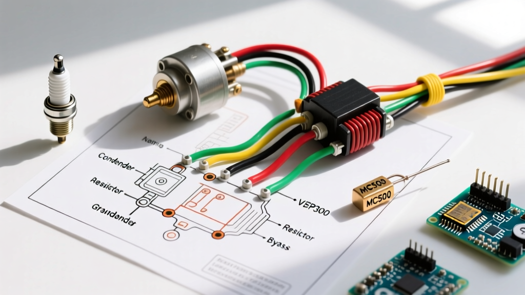

The Enduring Kettering System in Modern Restorations
Even as we navigate the advanced EV and EFI landscape of 2026, the classic Kettering points ignition system remains a cornerstone of vintage automotive and agricultural restoration. Whether you are resurrecting a 1967 Chevrolet Small Block V8 or rewiring a 1948 Ford 8N tractor, understanding the precise wiring diagram for points ignition is critical. Unlike modern solid-state HEI (High Energy Ignition) or coil-on-plug systems, a points-based system relies on a delicate mechanical and electrical balance. A single misrouted wire or an incorrectly specified ballast resistor will result in pitted contacts, a melted coil, or a complete failure to start.
This comprehensive guide breaks down the exact wiring topology, vehicle-specific variations, and component specifications required to build a reliable, factory-correct points ignition circuit.
Core Wiring Diagram for Points Ignition: Step-by-Step Flow
The fundamental Kettering circuit is divided into two distinct loops: the primary circuit (low voltage, high current) and the secondary circuit (high voltage, low current). Here is the exact current path for a standard 12-volt negative-ground system:
1. The Primary Circuit (12V to Ground)
- Battery Positive (+) feeds the ignition switch.
- Ignition Switch (Run Position) sends 12V to the input side of the ballast resistor (or resistance wire).
- Ballast Resistor drops the voltage to approximately 7V–9V and feeds the Coil Positive (+) terminal.
- Coil Primary Winding carries the current to the Coil Negative (-) terminal.
- Primary Wire (16-18 AWG) routes from the Coil (-) into the distributor, terminating at the movable point arm.
- Breaker Points act as a mechanical switch. When closed, current flows to the distributor base plate and grounds to the engine block.
2. The Secondary Circuit (High Voltage)
When the points open, the magnetic field in the coil collapses. The condenser (capacitor) absorbs the primary voltage spike, preventing arcing across the points and forcing the magnetic field to collapse rapidly. This induces a 20,000V+ pulse in the secondary winding, which exits the Coil Center Tower, travels through the high-tension coil wire to the distributor cap, and is routed by the rotor to the spark plugs.
Vehicle-Specific Wiring Variations
While the core physics remain identical, the physical wiring harness implementation varies drastically between classic American V8s and vintage agricultural tractors.
1955–1974 Chevrolet & Ford V8s (The Resistance Wire Harness)
Classic Detroit V8s rarely used a ceramic block ballast resistor on the firewall. Instead, they utilized a calibrated resistance wire integrated directly into the engine bay harness. This wire typically has a higher gauge (often 18 or 20 AWG) and a specific cloth or Hypalon jacketing designed to run hot.
Expert Warning: Never replace the factory resistance wire with standard 14 AWG copper wire. Doing so will send a full 12V–14.5V to a coil designed for 7V, causing the coil to overheat, boil its internal dielectric oil, and destroy the breaker points within 500 miles. For deeper insights into factory harness preservation, refer to the Hagerty Media ignition troubleshooting guide.
Vintage Tractors (Ford 8N, Farmall) & 6V-to-12V Conversions
Many vintage tractors originally left the factory with 6-volt positive-ground systems. In 2026, the vast majority of these have been converted to 12-volt negative-ground systems for reliability and parts availability. When executing a 12V conversion on a tractor with a points ignition, you must install an external ceramic ballast resistor (typically 1.2 to 1.5 ohms) between the ignition switch and the coil. Furthermore, ensure the coil is wired correctly: the Coil (+) must connect to the switched 12V source, and Coil (-) must connect to the distributor. Reversing this on a negative-ground system reduces spark intensity by up to 15%. The team at Yesterday's Tractors provides an excellent schematic reference for these specific 12V agricultural conversions.
Component Specifications & Selection Matrix
Selecting the correct coil and condenser is just as important as the wiring itself. Mismatched components are the leading cause of points failure. Use the matrix below to select your components based on your specific wiring diagram configuration.
| Component | Specification / Value | Application / Notes |
|---|---|---|
| Coil Primary Resistance | 1.2Ω – 1.5Ω | Standard 12V points coil (requires external ballast or resistance wire). |
| Coil Primary Resistance | 3.0Ω – 3.5Ω | "12V Electronic" or internal resistor coil (DO NOT use with external ballast). |
| Ballast Resistor | 1.2Ω – 1.5Ω (Ceramic) | Required for 1.5Ω coils on 12V systems to limit current to ~4 Amps. |
| Condenser Capacity | 0.15µF – 0.35µF | Standard is ~0.22µF. Too low = pitted points; Too high = weak spark. |
| Point Gap (V8) | 0.017" – 0.019" | Yields a dwell angle of approximately 28°–32°. |
| Point Gap (4/6 Cyl) | 0.020" – 0.022" | Yields a dwell angle of approximately 38°–48°. |
| Primary Wire Gauge | 14 AWG (Power), 16-18 AWG (Distributor) | Use stranded copper with high-temp insulation (e.g., TXL or GXL). |
The Starter Solenoid "I" Terminal Bypass (Crucial for V8s)
The most misunderstood aspect of the wiring diagram for points ignition in classic American V8s is the "I" (Ignition) terminal bypass. When the starter motor is engaged, it draws 150 to 250 amps, causing the vehicle's overall system voltage to drop from 12.6V down to 9V or lower. At 9V, a ballasted coil may not produce enough secondary voltage to fire the plugs under high cylinder compression.
The Solution: The starter solenoid features an "I" terminal that outputs full, unballasted battery voltage only while the solenoid is engaged (cranking). You must run a 14 AWG wire from the solenoid's "I" terminal directly to the Coil (+) terminal.
- During Cranking: The coil receives full 9V-10V directly from the "I" terminal, bypassing the ballast resistor, ensuring a hot spark.
- During Running: The solenoid disengages, the "I" terminal goes dead, and the coil receives its normal 7V-9V through the ignition switch and ballast resistor.
Note: Many modern mini-starters and aftermarket gear-reduction starters do not have an "I" terminal. In these cases, you must wire a standard 12V relay triggered by the starter "S" terminal to replicate this bypass circuit.
Diagnostic Troubleshooting & Failure Modes
When a points ignition system fails, the physical evidence on the breaker points and coil will tell you exactly what is wrong with the wiring. Consult this failure-mode guide before replacing parts:
1. Severely Pitted or Burned Points
- Cause: A failed or missing condenser, or system voltage exceeding 14.5V (faulty alternator regulator).
- Fix: Test the condenser with a multimeter set to Ohms. A good condenser will show a brief spike in resistance as it charges, then settle at infinite resistance (OL). Replace if shorted. Ensure the condenser wire is not touching the distributor housing, which would ground it out.
2. Coil Overheating and Swelling
- Cause: Missing ballast resistor, or using a 1.5Ω coil on a 12V system without a resistor. The coil is drawing 8+ amps instead of the designed 4 amps.
- Fix: With the engine running, use a multimeter to measure voltage at the Coil (+) terminal. It should read between 7.0V and 9.0V. If it reads 13.5V+, install a 1.5Ω ceramic ballast resistor immediately.
3. Engine Starts but Dies When Key is Released from "Start"
- Cause: The "I" terminal bypass wire is missing or broken, OR the ignition switch "Run" terminal is dead.
- Fix: Verify 12V at the input side of the ballast resistor with the key in the "Run" position. If zero, the ignition switch or harness is faulty. If 12V is present at the ballast input but 0V at the coil, the ballast resistor is burned open.
Authoritative References & Further Reading
For those diving deeper into the metallurgy of breaker points or the exact OEM harness routing for specific classic models, the following resources are highly recommended:
- Hemmings Motor News: Understanding Classic Car Ignition Systems – An excellent historical and technical breakdown of the Kettering system's evolution.
- Yesterday's Tractors: 12-Volt Conversions for Vintage Tractors – The definitive guide for agricultural 6V to 12V wiring, including coil polarity and ballast requirements.
- Society of Automotive Engineers (SAE): For rigorous academic standards on ignition coil inductance and dwell time parameters, refer to the SAE International technical papers archive on internal combustion ignition topologies.
By strictly adhering to this wiring diagram for points ignition and respecting the voltage requirements of the primary circuit, your classic V8 or vintage tractor will deliver reliable, factory-intended spark performance for decades to come.