
Why Transition to an Electric Stove in an RV or Camper Van?
As of 2026, the shift toward all-electric RVs, camper vans, and food trucks has accelerated dramatically. Driven by the banning of indoor propane combustion in several off-grid camping communities and the rise of high-capacity LiFePO4 battery banks, RV owners are increasingly seeking a reliable wiring diagram for electric stove installations. Whether you are retrofitting a Class B camper van with a Duxtop 9600LS induction cooktop or wiring a dedicated Greystone 24-inch RV electric range in a travel trailer, the electrical demands are immense.
An electric stove or induction cooktop typically draws between 1,500W and 1,800W per burner. In a residential home, this is a simple 120V/240V AC circuit. In a vehicle, however, you are pulling this power from a 12V, 24V, or 48V DC battery bank through an inverter. This requires meticulous wire gauge selection, proper overcurrent protection, and strict adherence to mobile electrical standards.
Core Electrical Requirements: Sizing Your System
Before laying out the wiring diagram, you must calculate the DC amperage draw. Many DIYers make the fatal mistake of sizing their wires based on the 120V AC amperage (e.g., 15 Amps) rather than the 12V DC amperage, which is exponentially higher.
| Stove / Cooktop Type | Max Wattage | 120V AC Draw | 12V DC Draw (Approx.) | Minimum Inverter Size | Recommended Battery Bank |
|---|---|---|---|---|---|
| Single Induction (e.g., NuWave PIC) | 1,300W | 10.8A | 120A | 2,000W | 200Ah LiFePO4 |
| Dual Induction (e.g., Duxtop 9600LS) | 1,800W (per burner) | 15.0A | 165A | 3,000W | 400Ah LiFePO4 |
| Greystone 24" RV Electric Range | 2,400W (total) | 20.0A | 220A | 3,000W - 4,000W | 400Ah+ LiFePO4 |
Note: DC draw calculations include a 10% buffer for inverter inefficiency. Always size your wiring for the maximum continuous draw, not the nominal draw.
The RV Wiring Diagram for Electric Stove: Step-by-Step Flow
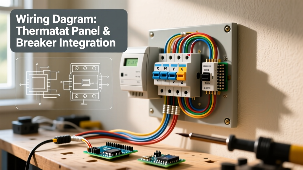
A safe and code-compliant vehicle wiring diagram for an electric stove is divided into two distinct zones: the high-current DC side and the 120V AC distribution side.
Phase 1: The DC High-Current Side (Battery to Inverter)
The connection between your battery bank and the inverter carries the heaviest load in the entire vehicle. For a standard 12V system powering an 1,800W induction stove via a 3,000W inverter, you are pushing upwards of 250 amps at peak surge.
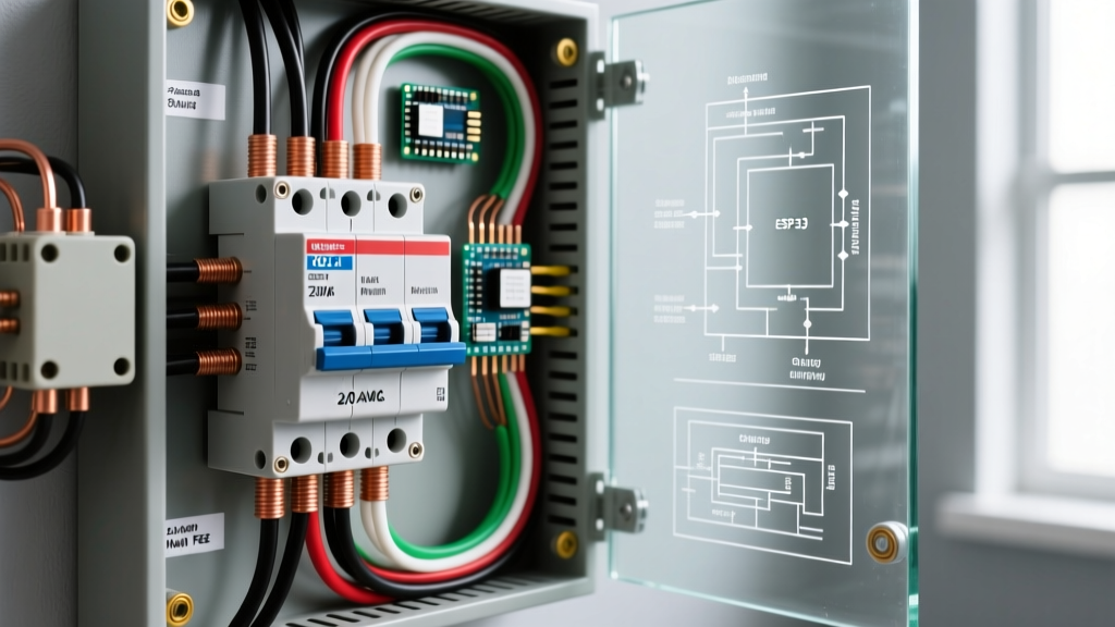
- Overcurrent Protection: Install a 250A or 300A Class T fuse or ANL fuse on the positive cable, within 7 inches of the battery bank positive terminal.
- Wire Gauge: Use 2/0 AWG (or 3/0 AWG for runs longer than 5 feet) pure copper, fine-stranded marine-grade wire. Aluminum wire is strictly prohibited in mobile applications due to vibration-induced work hardening and resistance spikes.
- Busbars: Route the positive and negative cables to a rated busbar (e.g., Blue Sea Systems 250A rated) before feeding the inverter to ensure clean, low-resistance connections.
Phase 2: The 120V AC Distribution Side (Inverter to Stove)
Once the power is inverted to 120V AC, it must pass through an AC breaker panel before reaching the stove. This is where the National Fire Protection Association (NFPA 70) standards, specifically adapted for mobile environments, come into play.
- Inverter AC Output: Wire the inverter's AC output directly to a dedicated AC sub-panel or the main RV distribution panel's inverter input.
- Breaker Sizing: Install a dedicated 20-Amp, double-pole or single-pole (depending on your inverter's split-phase capability) AC circuit breaker specifically for the stove circuit.
- AC Wiring: Run 12 AWG or 10 AWG THHN/THWN stranded copper wire from the 20A breaker to the stove's junction box.
- GFCI Protection: The first receptacle on the kitchen circuit, or the breaker itself, must be a GFCI (Ground Fault Circuit Interrupter) to protect against shock hazards in the presence of water and metal vehicle chassis grounds.
Wire Gauge and Breaker Selection Matrix
Proper wire sizing is critical to prevent voltage drop and thermal runaway. The Recreation Vehicle Industry Association (RVIA) mandates strict adherence to ampacity charts that account for the elevated ambient temperatures found inside RV walls and engine bays.
| Circuit Zone | Max Amperage | Recommended Wire Gauge (AWG) | Breaker / Fuse Type |
|---|---|---|---|
| 12V DC Battery to Inverter (Under 5 ft) | 250A | 2/0 AWG Copper | 300A Class T Fuse |
| 12V DC Battery to Inverter (5-10 ft) | 250A | 3/0 AWG Copper | 300A Class T Fuse |
| 48V DC Battery to Inverter (Modern 2026 Vans) | 65A | 6 AWG Copper | 80A ANL Fuse |
| 120V AC Inverter to Breaker Panel | 30A | 10 AWG Stranded | 30A AC Breaker |
| 120V AC Breaker to Electric Stove | 20A | 12 AWG Stranded | 20A GFCI Breaker |
The 48V DC Architecture Advantage for RV Stoves
If you are designing a new camper van build or food truck in 2026, consider adopting a 48V DC architecture. Running an 1,800W electric stove on a 12V system requires massive 2/0 AWG cables that are difficult to route through tight vehicle chassis spaces. By stepping up to a 48V battery bank and a 48V-to-120V inverter, the DC amperage drops from ~165A to roughly 40A. This allows you to use highly flexible 6 AWG wire for the DC side, drastically reducing installation time, weight, and voltage drop over distance.
Expert Insight: When routing AC and DC wires in a camper van, never run them parallel in the same conduit or loom. The electromagnetic interference (EMI) from the high-frequency inverter can induce noise in low-voltage DC control wires, potentially causing erratic behavior in smart battery management systems (BMS). Always separate AC and DC runs by at least 2 inches or use shielded cable.
Grounding, Bonding, and Chassis Safety
One of the most misunderstood aspects of the RV wiring diagram for electric stove setups is the grounding scheme. In a residential home, the neutral and ground are bonded at the main panel. In an RV or camper van, bonding the neutral and ground inside the inverter while simultaneously connecting to shore power can create a dangerous parallel neutral path, potentially energizing the vehicle chassis.
- Automatic Transfer Switch (ATS): Your inverter/charger must feature an internal ATS that automatically switches the neutral-ground bond depending on whether the vehicle is running on shore power or inverter power.
- Chassis Grounding: The stove's metal chassis and the AC ground wire (bare copper or green) must be tied back to the AC grounding busbar in the distribution panel, which ultimately bonds to the vehicle's metal chassis via a dedicated grounding lug.
Common Failure Modes and Troubleshooting
Even with a perfect wiring diagram, real-world vehicle conditions introduce edge cases. Here are the most common failure modes when operating an electric stove off-grid:
1. Inverter Overload and Thermal Shutdown
Symptom: The stove works on low settings but shuts off the entire inverter when turned to 'High' or 'Boost'.
Cause: Induction cooktops use high-frequency magnetic fields that create a poor power factor. An 1,800W cooktop might actually draw 2,200W of apparent power (VA). If your inverter is only rated for 2,000W continuous, it will trip.
Fix: Upgrade to a low-frequency or high-surge high-frequency inverter rated for at least 3,000W continuous / 6,000W surge, and ensure adequate ventilation for the inverter's cooling fans.
2. Nuisance GFCI Tripping
Symptom: The stove's GFCI breaker trips randomly, especially when the vehicle's water pump or compressor fridge kicks on.
Cause: Induction cooktops generate high-frequency electrical noise that can leak to ground, which sensitive RV GFCI breakers interpret as a ground fault.
Fix: Use a GFCI breaker specifically designed for high-EMI environments, or ensure the cooktop's internal EMI filter is intact. Avoid using modified sine wave (MSW) inverters; always use a pure sine wave inverter to minimize harmonic distortion.
3. Severe Voltage Sag
Symptom: The stove's digital display flickers, and the BMS cuts power entirely.
Cause: Undersized DC wiring or loose terminal connections causing a voltage drop below the inverter's low-voltage disconnect (LVD) threshold (usually 10.5V for 12V systems).
Fix: Check all busbar connections with a torque wrench. Re-crimp any DC lugs using a proper hydraulic crimping tool and seal them with adhesive-lined heat shrink to prevent oxidation.
Final Safety Inspections
Before energizing the circuit, perform a continuity test on the AC ground wire from the stove chassis to the vehicle's main ground busbar. Verify that the resistance is less than 0.5 ohms. Once energized, use a clamp meter to measure the DC current draw on the positive battery cable while the stove is operating at maximum capacity. If the wire feels warm to the touch after 10 minutes of continuous use, your wire gauge is insufficient for the ambient temperature of your specific vehicle build, and you must upsize the cable immediately.