
Understanding the Standard Wiring Diagram for Boat Trailer Lights
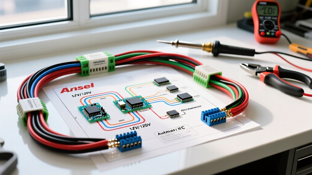
Whether you are launching a 14-foot aluminum jon boat or hauling a 26-foot center console, a reliable lighting harness is non-negotiable for safety and legal compliance. In the United States, trailer lighting is strictly governed by Federal Motor Vehicle Safety Standard (FMVSS) 108, which mandates specific visibility requirements for taillights, brake lights, and turn signals. For 90% of recreational boat trailers under 80 inches wide, the standard 4-way flat or 5-way flat connector provides the exact circuit pathways required by law.
As of 2026, the marine industry has almost entirely transitioned from incandescent bulbs to sealed LED submersible fixtures (such as the Optronics STL36RB or Submersible LED Trailer Light kits). While LEDs draw significantly less current and run cooler, they introduce new wiring considerations regarding voltage drop, hyperflashing, and galvanic corrosion. This guide provides the exact wiring diagram for boat trailer lights, material specifications, and professional troubleshooting matrices to ensure your harness survives repeated saltwater submersion.
The 4-Way Flat Wiring Diagram: Pinout and Circuit Functions
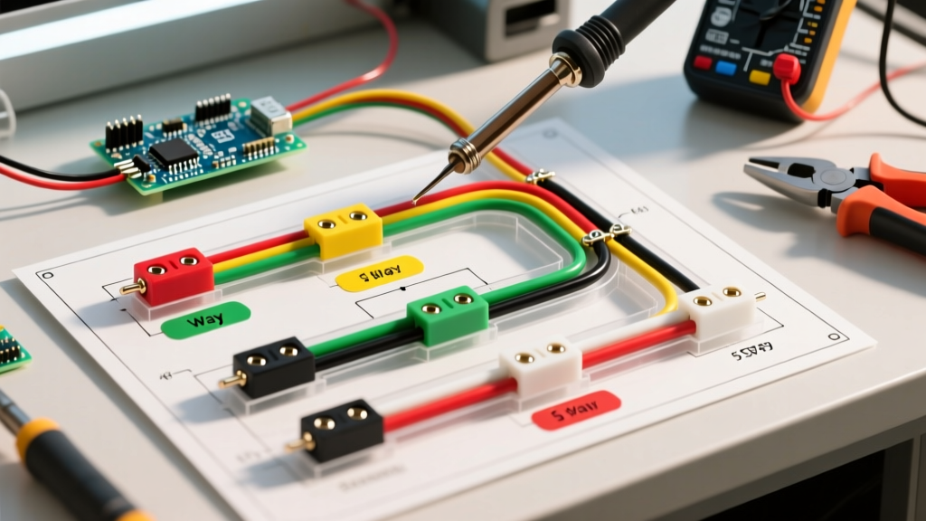
The 4-way flat connector is the undisputed industry standard for basic boat trailers. It utilizes a wishbone-style harness where the running light circuit splits into two separate wires to feed both sides of the trailer. Below is the standardized pinout configuration recognized by the Society of Automotive Engineers (SAE) and major hitch manufacturers.
| Pin Position | Wire Color | Circuit Function | Avg. LED Draw (2026) | Avg. Halogen Draw |
|---|---|---|---|---|
| Pin 1 (Exposed/Ground) | White | Chassis Ground Return | N/A | N/A |
| Pin 2 (Left/Inner) | Brown | Taillights / Running Lights | 0.2A - 0.5A | 2.5A - 4.0A |
| Pin 3 (Middle) | Yellow | Left Turn Signal & Brake Light | 0.8A - 1.2A | 4.0A - 5.5A |
| Pin 4 (Right/Outer) | Green | Right Turn Signal & Brake Light | 0.8A - 1.2A | 4.0A - 5.5A |
Pro-Tip for 4-Way Harnesses: Never rely on the hitch ball for your primary ground. The white wire (Pin 1) must be securely ring-terminated and bolted directly to the trailer's steel or aluminum frame near the tongue to complete the circuit back to the tow vehicle's battery.
Upgrading to the 5-Way Flat Connector for Surge Brakes
If your boat trailer is equipped with hydraulic surge brakes (common on tandem-axle trailers over 3,000 lbs GVWR), you will need a 5-way flat connector. The wiring diagram for boat trailer lights with surge brakes adds a crucial fifth circuit.
- Pin 5 (Blue Wire): Reverse Light / Brake Lockout Circuit.
When you shift your tow vehicle into reverse, the blue wire sends 12V power to the reverse lockout solenoid on the trailer's surge brake actuator. This prevents the brakes from engaging while you are backing down the boat ramp. If you are adapting a 4-way vehicle plug to a 5-way trailer plug, you must splice the blue wire into your tow vehicle's reverse light circuit, typically found at the tail light housing or the upfitter switch bank.
Wire Gauge Selection & Marine-Grade Materials
The harsh marine environment demands specific material choices. Standard automotive copper-clad aluminum (CCA) wire will oxidize and turn to green powder within a single season of saltwater exposure. For a permanent wiring diagram for boat trailer lights, you must use tinned marine-grade copper wire (e.g., Ancor Marine Grade 112516).
2026 Wire Sizing Guidelines
- 16 AWG Tinned Copper: Sufficient for all-LED trailers under 20 feet in length. Handles up to 10A safely. Cost: ~$1.15 per foot.
- 14 AWG Tinned Copper: Mandatory for incandescent setups, trailers over 20 feet, or setups utilizing auxiliary guide poles and clearance lights. Mitigates voltage drop over long runs. Cost: ~$1.60 per foot.
- 12 AWG Tinned Copper: Reserved exclusively for the main power feed on trailers with electric-over-hydraulic (EOH) brake controllers or heavy winch charging lines.
Termination and Splicing Standards
Avoid twisting wires and wrapping them in vinyl electrical tape. Vinyl tape degrades in UV light and traps moisture, accelerating corrosion. Instead, use adhesive-lined polyolefin heat shrink butt connectors (such as 3M 560-BT or Knoweasy marine assortments). When heated to 250°F, the inner adhesive melts and seals the crimp, creating a 100% waterproof barrier. Use a dedicated ratcheting crimping tool (like the IWISS IWS-16) to ensure a gas-tight mechanical connection before applying heat.
The "White Wire" Grounding Rule: Avoiding the 80% Failure Point
According to marine mechanics, over 80% of boat trailer lighting failures are not caused by blown bulbs or broken wires, but by poor grounding. The wiring diagram for boat trailer lights relies on the trailer frame to carry the return current back to the tow vehicle. If the frame is painted, powder-coated, or heavily rusted, the circuit will seek alternative paths, resulting in "backfeeding" (e.g., hitting the brakes causes the running lights to dimly illuminate).
- Locate the Ground Point: Choose a spot on the trailer tongue within 12 inches of the hitch coupler.
- Prepare the Metal: Use a wire wheel or 80-grit sandpaper to strip away all paint, galvanization, and rust down to bare, shiny metal.
- Apply the Terminal: Crimp a heavy-duty ring terminal onto the white ground wire.
- Secure with Hardware: Bolt the terminal using a stainless steel hex bolt, a flat washer, a star washer (to bite into the metal and prevent vibration loosening), and a nylon-insert lock nut.
Seal the Connection: Smear the entire terminal assembly with marine-grade dielectric grease or fluid film to prevent future oxidation.
LED Hyperflashing and Load Resistors
When upgrading an older boat trailer from incandescent to LED lights, you may encounter "hyperflashing" (turn signals blinking twice as fast). This happens because modern tow vehicle flasher relays monitor circuit resistance. Since LEDs draw roughly 80% less current than halogens, the vehicle's computer assumes a bulb is burned out and speeds up the flash rate to warn the driver.
To fix this without replacing your vehicle's flasher relay, install load resistors (such as the Tow Ready 54158 or generic 50W 6-Ohm aluminum resistors). Splice one resistor in parallel on the yellow wire (left turn) and one on the green wire (right turn). Warning: These resistors generate significant heat (up to 150°F). Mount them securely to the trailer frame using metal screws, keeping them away from plastic wire looms and the harness sheathing.
Troubleshooting Matrix: Symptoms, Causes, and Fixes
When your trailer lights fail at the ramp, you need a systematic approach. Use a digital multimeter (such as the Fluke 115 or similar true-RMS meter) to test for voltage drop and continuity. Refer to the matrix below for rapid diagnostics.
| Symptom | Probable Cause | Diagnostic Step & Fix |
|---|---|---|
| Running lights are completely dead; turn signals work. | Blown fuse in tow vehicle or broken brown wire. | Check tow vehicle's trailer tow fuse. Probe Pin 2 (brown) at the vehicle plug with a test light. If 12V is present, trace the brown wire on the trailer for a pinch point or cut. |
| Brakes and turn signals work, but dimly; running lights flicker. | Poor chassis ground (White wire). | Run a temporary jumper wire from the trailer frame directly to the vehicle's negative battery terminal. If lights normalize, clean and re-terminate the white ground wire on the trailer tongue. |
| Hitting the brakes turns on ALL trailer lights dimly. | Backfeeding due to a missing or corroded ground. | The current is backfeeding through the dual-filament bulbs. Inspect the ground ring terminal and ensure the star washer is biting into bare metal, not paint or rust. |
| Surge brakes engage when backing down the ramp. | Reverse lockout solenoid failure or blue wire disconnect. | Verify 12V at the 5th pin (blue) when the vehicle is in reverse. If voltage is present, the solenoid on the brake actuator is seized and requires replacement. |
| One side's turn signal blinks rapidly on the dash. | LED hyperflash or corroded bulb socket. | If using LEDs, install a 6-Ohm load resistor on the affected side's turn wire. If using halogens, replace the bulb and clean the socket contacts with electrical contact cleaner. |
Final Inspection and Submersion Protocol
Before backing your boat trailer into the water, perform a final "walk-around" voltage check. Ensure all heat-shrink splices are fully sealed and that no bare copper is exposed to the elements. If you are using submersible LED lights, verify that the manufacturer's drain holes (usually located at the bottom of the light housing) are facing downward and are not clogged with road grime. These holes allow water to drain out when the trailer is pulled from the lake, preventing internal condensation from destroying the LED driver boards. By adhering strictly to this wiring diagram for boat trailer lights and utilizing marine-grade tinned components, your lighting harness will provide years of reliable, legal, and safe service.